Dell PowerVault DL2200 Hardware Owner's Manual - Page 15
Back-Panel Features and Indicators
 |
View all Dell PowerVault DL2200 manuals
Add to My Manuals
Save this manual to your list of manuals |
Page 15 highlights
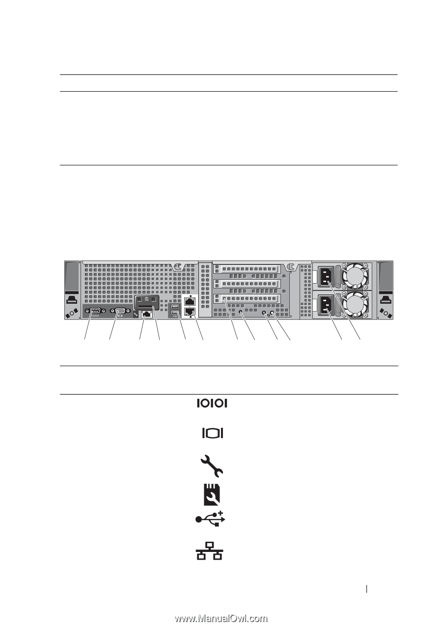
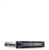
Drive-Status Indicator Pattern Blinks green slowly Steady green Blinks green three seconds, off three seconds, amber three seconds, and off three seconds Condition Drive rebuilding Drive online Rebuild aborted Back-Panel Features and Indicators Figure 1-3 shows the controls, indicators, and connectors located on the back panel of the system. Figure 1-3. Back-Panel Features and Indicators ST 1 1 2 Gb 1 2 3 Gb 2 12 3 4 56 Item Indicator, Button, or Icon Connector 1 Serial connector 2 Video connector 3 iDRAC6 Enterprise port (optional) 4 VFlash media slot (optional) 5 USB connectors (2) 6 Ethernet connectors (2) 7 8 9 10 11 12 Description Connects a serial device to the system. Connects a VGA display to the system. Dedicated management port for the optional iDRAC6 Enterprise card. Connects an external SD memory card for the optional iDRAC6 Enterprise card. Connect USB devices to the system. The ports are USB 2.0-compliant. Embedded 10/100/1000 NIC connectors. About Your System 15
-
 1
1 -
2
-
3
-
4
-
5
-
6
-
7
-
8
-
9
-
 10
10 -
 11
11 -
 12
12 -
 13
13 -
 14
14 -
 15
15 -
 16
16 -
 17
17 -
 18
18 -
 19
19 -
 20
20 -
21
-
22
-
23
-
24
-
25
-
26
-
27
-
28
-
29
-
30
-
31
-
32
-
33
-
34
-
35
-
36
-
37
-
38
-
39
-
40
-
41
-
42
-
43
-
44
-
45
-
46
-
47
-
48
-
49
-
50
-
51
-
52
-
53
-
54
-
55
-
56
-
57
-
58
-
59
-
60
-
61
-
62
-
63
-
64
-
65
-
66
-
67
-
68
-
69
-
70
-
71
-
72
-
73
-
74
-
75
-
76
-
77
-
78
-
79
-
80
-
81
-
82
-
83
-
84
-
85
-
86
-
87
-
88
-
89
-
90
-
91
-
92
-
93
-
94
-
95
-
96
-
97
-
98
-
99
-
100
-
101
-
102
-
103
-
104
-
105
-
106
-
107
-
108
-
109
-
110
-
111
-
112
-
113
-
114
-
115
-
116
-
117
-
118
-
119
-
120
-
121
-
122
-
123
-
124
-
125
-
126
-
127
-
128
-
129
-
130
-
131
-
132
-
133
-
134
-
135
-
136
-
137
-
138
-
139
-
140
-
141
-
142
-
143
-
144
-
145
-
146
-
147
-
148
-
149
-
150
-
151
-
152
-
153
-
154
-
155
-
156
-
157
-
158
-
159
-
160
-
161
-
162
-
163
-
164
 |
 |