Dell PowerVault DL2200 Hardware Owner's Manual - Page 77
Replacing a Cooling Fan, Power Supplies
 |
View all Dell PowerVault DL2200 manuals
Add to My Manuals
Save this manual to your list of manuals |
Page 77 highlights
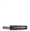
Replacing a Cooling Fan CAUTION: Many repairs may only be done by a certified service technician. You should only perform troubleshooting and simple repairs as authorized in your product documentation, or as directed by the online or telephone service and support team. Damage due to servicing that is not authorized by Dell is not covered by your warranty. Read and follow the safety instructions that came with the product. 1 Align the fan module so that the side with the power cable faces toward the back of the system. 2 Slide the fan module into the fan assembly until the fan is fully seated. See Figure 3-10. 3 Connect the fan's power cable to the power connector on the system board. 4 Replace the internal hard-drive carrier and bay. See "Installing an Internal Hard Drive Bay" on page 73. 5 Route the power cable through the guides on the chassis. 6 Replace the cooling shroud. See "Installing the Cooling Shroud" on page 67. 7 Close the system. See "Closing the System" on page 65. 8 Reconnect the system to its electrical outlet and turn the system on, including any attached peripherals. Power Supplies Your system supports two 750 W redundant power supply modules. NOTE: The maximum output power (shown in watts) is listed on the power supply label. If two power supplies are installed, the second power supply provides hot-swappable, power redundancy. In redundant mode, the system distributes the power load across both power supplies to maximize efficiency. When a power supply is removed with the system powered on, the full power load is picked up by the remaining power supply. CAUTION: To ensure proper system cooling, the power supply blank must be installed in the PS2 bay. See "Installing the Power Supply Blank" on page 80". Installing System Components 77
-
 1
1 -
2
-
3
-
4
-
5
-
6
-
7
-
8
-
9
-
10
-
11
-
12
-
13
-
14
-
15
-
16
-
17
-
18
-
19
-
20
-
21
-
22
-
23
-
24
-
25
-
26
-
27
-
28
-
29
-
30
-
31
-
32
-
33
-
34
-
35
-
36
-
37
-
38
-
39
-
40
-
41
-
42
-
43
-
44
-
45
-
46
-
47
-
48
-
49
-
50
-
51
-
52
-
53
-
54
-
55
-
56
-
57
-
58
-
59
-
60
-
61
-
62
-
63
-
64
-
65
-
66
-
67
-
68
-
69
-
70
-
71
-
 72
72 -
 73
73 -
 74
74 -
 75
75 -
 76
76 -
 77
77 -
 78
78 -
 79
79 -
 80
80 -
 81
81 -
 82
82 -
83
-
84
-
85
-
86
-
87
-
88
-
89
-
90
-
91
-
92
-
93
-
94
-
95
-
96
-
97
-
98
-
99
-
100
-
101
-
102
-
103
-
104
-
105
-
106
-
107
-
108
-
109
-
110
-
111
-
112
-
113
-
114
-
115
-
116
-
117
-
118
-
119
-
120
-
121
-
122
-
123
-
124
-
125
-
126
-
127
-
128
-
129
-
130
-
131
-
132
-
133
-
134
-
135
-
136
-
137
-
138
-
139
-
140
-
141
-
142
-
143
-
144
-
145
-
146
-
147
-
148
-
149
-
150
-
151
-
152
-
153
-
154
-
155
-
156
-
157
-
158
-
159
-
160
-
161
-
162
-
163
-
164
 |
 |