Dell PowerVault DL2200 Hardware Owner's Manual - Page 86
the memory module socket snap in place., When the memory module is properly seated in the socket
 |
View all Dell PowerVault DL2200 manuals
Add to My Manuals
Save this manual to your list of manuals |
Page 86 highlights
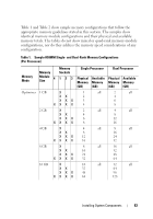
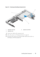
Figure 3-12. Removing and Installing a Memory Module 1 2 3 1 memory module 3 alignment key 2 memory module socket ejectors (2) 7 Align the memory module's edge connector with the alignment key of the memory module socket, and insert the memory module in the socket. NOTE: The memory module socket has an alignment key that allows you to install the memory module in the socket in only one way. 8 Press down on the memory module with your thumbs to lock the memory module into the socket. When the memory module is properly seated in the socket, the ejectors on the memory module socket snap in place. 9 Repeat step 5 through step 8 of this procedure to install the remaining memory modules. See Table 2. 10 Replace the cooling shroud. See "Installing the Cooling Shroud" on page 67. 11 Close the system. See "Closing the System" on page 65. 86 Installing System Components
-
 1
1 -
2
-
3
-
4
-
5
-
6
-
7
-
8
-
9
-
10
-
11
-
12
-
13
-
14
-
15
-
16
-
17
-
18
-
19
-
20
-
21
-
22
-
23
-
24
-
25
-
26
-
27
-
28
-
29
-
30
-
31
-
32
-
33
-
34
-
35
-
36
-
37
-
38
-
39
-
40
-
41
-
42
-
43
-
44
-
45
-
46
-
47
-
48
-
49
-
50
-
51
-
52
-
53
-
54
-
55
-
56
-
57
-
58
-
59
-
60
-
61
-
62
-
63
-
64
-
65
-
66
-
67
-
68
-
69
-
70
-
71
-
72
-
73
-
74
-
75
-
76
-
77
-
78
-
79
-
80
-
 81
81 -
 82
82 -
 83
83 -
 84
84 -
 85
85 -
 86
86 -
 87
87 -
 88
88 -
 89
89 -
 90
90 -
 91
91 -
92
-
93
-
94
-
95
-
96
-
97
-
98
-
99
-
100
-
101
-
102
-
103
-
104
-
105
-
106
-
107
-
108
-
109
-
110
-
111
-
112
-
113
-
114
-
115
-
116
-
117
-
118
-
119
-
120
-
121
-
122
-
123
-
124
-
125
-
126
-
127
-
128
-
129
-
130
-
131
-
132
-
133
-
134
-
135
-
136
-
137
-
138
-
139
-
140
-
141
-
142
-
143
-
144
-
145
-
146
-
147
-
148
-
149
-
150
-
151
-
152
-
153
-
154
-
155
-
156
-
157
-
158
-
159
-
160
-
161
-
162
-
163
-
164
 |
 |
