Dell PowerVault DL2200 Hardware Owner's Manual - Page 16
external PCI Express Generation 2, Power supply 1 PS1
 |
View all Dell PowerVault DL2200 manuals
Add to My Manuals
Save this manual to your list of manuals |
Page 16 highlights
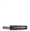
Item Indicator, Button, or Icon Connector 7 PCIe expansion card slots using riser card 8 System identification connector 9 System status indicator 10 System identification button 11 Power supply 2 (PS2) 12 Power supply 1 (PS1) Description Connects one internal and three external PCI Express Generation 2 expansion cards. Slot 1: PCIe x4, half-length, full-height Slot 2: PCIe x4, full-length, full-height Slot 3: PCIe x8, half-length, full-height Slot 4: PCIe x4, internal slot for integrated card NOTE: All four slots are x8 connectors. Connects the optional system status indicator assembly through the optional cable management arm. Lights blue during normal system operation. Both the systems management software and the identification buttons located on the front and back of the system can cause the indicator to blink blue to identify a particular system. Lights amber when the system needs attention due to a problem. The identification buttons on the front and back panels can be used to locate a particular system within a rack. When one of these buttons is pushed, the blue system status indicator on the chassis back blinks until one of the buttons is pushed again. 750 W/1100 W redundant power supply 750 W/1100 W redundant power supply 16 About Your System
-
 1
1 -
2
-
3
-
4
-
5
-
6
-
7
-
8
-
9
-
10
-
 11
11 -
 12
12 -
 13
13 -
 14
14 -
 15
15 -
 16
16 -
 17
17 -
 18
18 -
 19
19 -
 20
20 -
 21
21 -
22
-
23
-
24
-
25
-
26
-
27
-
28
-
29
-
30
-
31
-
32
-
33
-
34
-
35
-
36
-
37
-
38
-
39
-
40
-
41
-
42
-
43
-
44
-
45
-
46
-
47
-
48
-
49
-
50
-
51
-
52
-
53
-
54
-
55
-
56
-
57
-
58
-
59
-
60
-
61
-
62
-
63
-
64
-
65
-
66
-
67
-
68
-
69
-
70
-
71
-
72
-
73
-
74
-
75
-
76
-
77
-
78
-
79
-
80
-
81
-
82
-
83
-
84
-
85
-
86
-
87
-
88
-
89
-
90
-
91
-
92
-
93
-
94
-
95
-
96
-
97
-
98
-
99
-
100
-
101
-
102
-
103
-
104
-
105
-
106
-
107
-
108
-
109
-
110
-
111
-
112
-
113
-
114
-
115
-
116
-
117
-
118
-
119
-
120
-
121
-
122
-
123
-
124
-
125
-
126
-
127
-
128
-
129
-
130
-
131
-
132
-
133
-
134
-
135
-
136
-
137
-
138
-
139
-
140
-
141
-
142
-
143
-
144
-
145
-
146
-
147
-
148
-
149
-
150
-
151
-
152
-
153
-
154
-
155
-
156
-
157
-
158
-
159
-
160
-
161
-
162
-
163
-
164
 |
 |
