HP 6125G HP 6125G & 6125G/XG Blade Switches Layer 3 - IP Routing Confi - Page 123
Configuring BFD for OSPF, Network requirements, Configuration procedure, Network diagram
 |
View all HP 6125G manuals
Add to My Manuals
Save this manual to your list of manuals |
Page 123 highlights
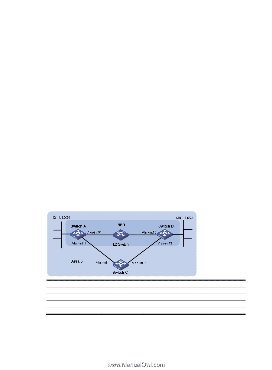
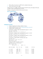
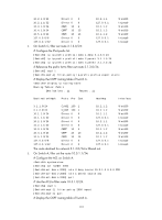
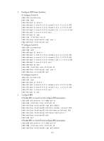
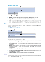
[SwitchA] display ip routing-table Routing Tables: Public Destinations : 10 Routes : 10 Destination/Mask Proto Pre Cost NextHop Interface 3.1.1.0/24 O_ASE 150 1 3.1.2.0/24 O_ASE 150 1 10.1.1.0/24 Direct 0 0 10.1.1.1/32 Direct 0 0 10.2.1.0/24 Direct 0 0 10.2.1.1/32 Direct 0 0 10.3.1.0/24 OSPF 10 4 10.4.1.0/24 OSPF 10 13 127.0.0.0/8 Direct 0 0 127.0.0.1/32 Direct 0 0 The route destined for 10.5.1.1/24 is filtered out. 10.2.1.2 10.2.1.2 10.1.1.1 127.0.0.1 10.2.1.1 127.0.0.1 10.1.1.2 10.2.1.2 127.0.0.1 127.0.0.1 Vlan200 Vlan200 Vlan100 InLoop0 Vlan200 InLoop0 Vlan100 Vlan200 InLoop0 InLoop0 Configuring BFD for OSPF Network requirements As shown in Figure 42, OSPF is enabled on Switch A, Switch B and Switch C that are reachable to each other at the network layer. After the link over which Switch A and Switch B communicate through a Layer 2 switch fails, BFD can quickly detect the failure and notify OSPF of the failure. Switch A and Switch B then communicate through Switch C. Figure 42 Network diagram Device Switch A Switch C Interface Vlan-int10 Vlan-int11 Vlan-int11 Vlan-int13 IP address 10.1.0.102/24 11.1.1.1/24 11.1.1.2/24 13.1.1.2/24 Device Switch B Interface Vlan-int10 Vlan-int13 Configuration procedure 1. Configure IP addresses for interfaces. (Details not shown.) IP address 10.1.0.100/24 13.1.1.1/24 113
-
 1
1 -
2
-
3
-
4
-
5
-
6
-
7
-
8
-
9
-
10
-
11
-
12
-
13
-
14
-
15
-
16
-
17
-
18
-
19
-
20
-
21
-
22
-
23
-
24
-
25
-
26
-
27
-
28
-
29
-
30
-
31
-
32
-
33
-
34
-
35
-
36
-
37
-
38
-
39
-
40
-
41
-
42
-
43
-
44
-
45
-
46
-
47
-
48
-
49
-
50
-
51
-
52
-
53
-
54
-
55
-
56
-
57
-
58
-
59
-
60
-
61
-
62
-
63
-
64
-
65
-
66
-
67
-
68
-
69
-
70
-
71
-
72
-
73
-
74
-
75
-
76
-
77
-
78
-
79
-
80
-
81
-
82
-
83
-
84
-
85
-
86
-
87
-
88
-
89
-
90
-
91
-
92
-
93
-
94
-
95
-
96
-
97
-
98
-
99
-
100
-
101
-
102
-
103
-
104
-
105
-
106
-
107
-
108
-
109
-
110
-
111
-
112
-
113
-
114
-
115
-
116
-
117
-
 118
118 -
 119
119 -
 120
120 -
 121
121 -
 122
122 -
 123
123 -
 124
124 -
 125
125 -
 126
126 -
 127
127 -
 128
128 -
129
-
130
-
131
-
132
-
133
-
134
-
135
-
136
-
137
-
138
-
139
-
140
-
141
-
142
-
143
-
144
-
145
-
146
-
147
-
148
-
149
-
150
-
151
-
152
-
153
-
154
-
155
-
156
-
157
-
158
-
159
-
160
-
161
-
162
-
163
-
164
-
165
-
166
-
167
-
168
-
169
-
170
-
171
-
172
-
173
-
174
-
175
-
176
-
177
-
178
-
179
-
180
-
181
-
182
-
183
-
184
-
185
-
186
-
187
-
188
-
189
-
190
-
191
-
192
-
193
-
194
-
195
-
196
-
197
-
198
-
199
-
200
-
201
-
202
-
203
-
204
-
205
-
206
-
207
-
208
-
209
-
210
-
211
-
212
-
213
-
214
-
215
-
216
-
217
-
218
-
219
-
220
-
221
-
222
-
223
-
224
-
225
-
226
-
227
-
228
-
229
-
230
-
231
-
232
-
233
-
234
-
235
-
236
-
237
-
238
-
239
-
240
-
241
-
242
-
243
-
244
-
245
-
246
-
247
-
248
-
249
-
250
-
251
-
252
-
253
-
254
-
255
-
256
-
257
-
258
-
259
-
260
-
261
-
262
-
263
-
264
-
265
-
266
-
267
-
268
-
269
-
270
-
271
-
272
-
273
-
274
-
275
-
276
-
277
-
278
-
279
-
280
-
281
-
282
-
283
-
284
-
285
-
286
-
287
-
288
-
289
-
290
-
291
-
292
-
293
-
294
-
295
-
296
-
297
-
298
-
299
-
300
-
301
-
302
-
303
-
304
-
305
-
306
-
307
-
308
-
309
-
310
-
311
-
312
 |
 |