HP 6125G HP 6125G & 6125G/XG Blade Switches Layer 3 - IP Routing Confi - Page 281
Configuring routing on an MCE, Route exchange between an MCE and a VPN site
 |
View all HP 6125G manuals
Add to My Manuals
Save this manual to your list of manuals |
Page 281 highlights
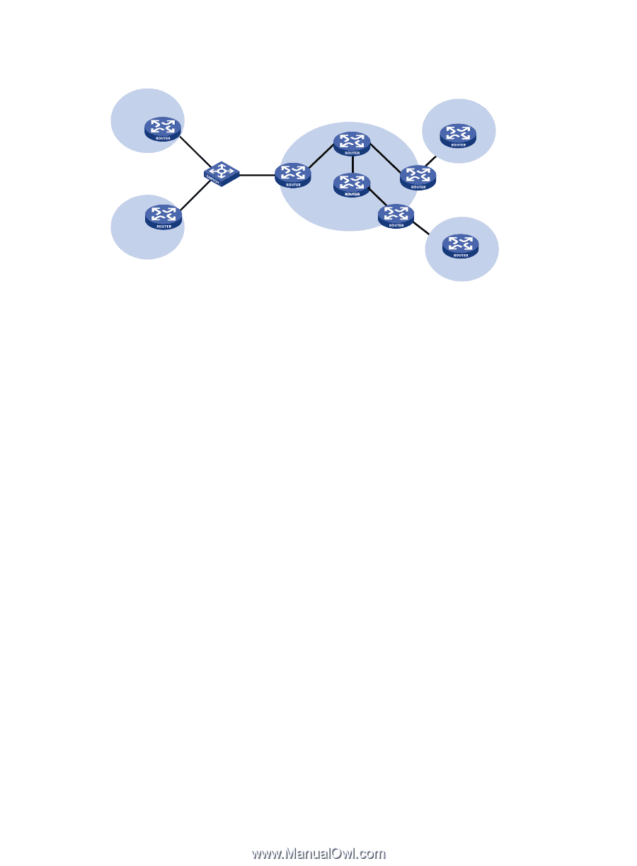
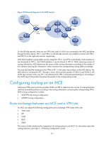
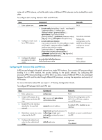
Figure 87 Network diagram for the MCE function VPN 1 Site 1 P VPN 2 Site 2 VLAN-int2 VLAN-int7 VLAN-int8 VLAN-int3 MCE PE1 P PE VPN 2 Site 1 CE PE2 CE Site 2 VPN 1 On the left-side network, there are two VPN sites, both of which are connected to the MPLS backbone through the MCE device. VPN 1 and VPN 2 on the left-side network must establish a tunnel with VPN 1 and VPN 2 on the right-side network, respectively. With MCE enabled, routing tables can be created for VPN 1 and VPN 2 individually, VLAN-interface 2 can be bound to VPN 1, and VLAN-interface 3 can be bound to VPN 2. When receiving a piece of routing information, MCE determines the source of the routing information according to the number of the interface receiving the information. It then maintains the corresponding routing table accordingly. You must also bind the interfaces to the VPNs on PE 1 in the same way as those on the MCE device. The MCE device is connected to PE 1 through a trunk, which permits packets of VLAN 2 and VLAN 3 with VLAN tags carried. In this way, PE 1 can determine the VPN a received packet belongs to according to the VLAN tag of the packet and passes the packet to the corresponding tunnel. Configuring routing on an MCE Interface-to-VPN-instance binding enables MCEs and PEs to determine the sources of received packets and then forward the packets according to the routing information concerning the corresponding VPNs. MCE routing configuration includes: • MCE-VPN site routing configuration • MCE-PE routing configuration Route exchange between an MCE and a VPN site An MCE can adopt the following routing protocols to exchange VPN routes with a site: • Static route • RIP • OSPF • IBGP • EBGP This section briefly introduces the cooperation of routing protocols and MCE. For information about the routing protocols, see Layer 3-IP Routing Configuration Guide. 271
-
 1
1 -
2
-
3
-
4
-
5
-
6
-
7
-
8
-
9
-
10
-
11
-
12
-
13
-
14
-
15
-
16
-
17
-
18
-
19
-
20
-
21
-
22
-
23
-
24
-
25
-
26
-
27
-
28
-
29
-
30
-
31
-
32
-
33
-
34
-
35
-
36
-
37
-
38
-
39
-
40
-
41
-
42
-
43
-
44
-
45
-
46
-
47
-
48
-
49
-
50
-
51
-
52
-
53
-
54
-
55
-
56
-
57
-
58
-
59
-
60
-
61
-
62
-
63
-
64
-
65
-
66
-
67
-
68
-
69
-
70
-
71
-
72
-
73
-
74
-
75
-
76
-
77
-
78
-
79
-
80
-
81
-
82
-
83
-
84
-
85
-
86
-
87
-
88
-
89
-
90
-
91
-
92
-
93
-
94
-
95
-
96
-
97
-
98
-
99
-
100
-
101
-
102
-
103
-
104
-
105
-
106
-
107
-
108
-
109
-
110
-
111
-
112
-
113
-
114
-
115
-
116
-
117
-
118
-
119
-
120
-
121
-
122
-
123
-
124
-
125
-
126
-
127
-
128
-
129
-
130
-
131
-
132
-
133
-
134
-
135
-
136
-
137
-
138
-
139
-
140
-
141
-
142
-
143
-
144
-
145
-
146
-
147
-
148
-
149
-
150
-
151
-
152
-
153
-
154
-
155
-
156
-
157
-
158
-
159
-
160
-
161
-
162
-
163
-
164
-
165
-
166
-
167
-
168
-
169
-
170
-
171
-
172
-
173
-
174
-
175
-
176
-
177
-
178
-
179
-
180
-
181
-
182
-
183
-
184
-
185
-
186
-
187
-
188
-
189
-
190
-
191
-
192
-
193
-
194
-
195
-
196
-
197
-
198
-
199
-
200
-
201
-
202
-
203
-
204
-
205
-
206
-
207
-
208
-
209
-
210
-
211
-
212
-
213
-
214
-
215
-
216
-
217
-
218
-
219
-
220
-
221
-
222
-
223
-
224
-
225
-
226
-
227
-
228
-
229
-
230
-
231
-
232
-
233
-
234
-
235
-
236
-
237
-
238
-
239
-
240
-
241
-
242
-
243
-
244
-
245
-
246
-
247
-
248
-
249
-
250
-
251
-
252
-
253
-
254
-
255
-
256
-
257
-
258
-
259
-
260
-
261
-
262
-
263
-
264
-
265
-
266
-
267
-
268
-
269
-
270
-
271
-
272
-
273
-
274
-
275
-
 276
276 -
 277
277 -
 278
278 -
 279
279 -
 280
280 -
 281
281 -
 282
282 -
 283
283 -
 284
284 -
 285
285 -
 286
286 -
287
-
288
-
289
-
290
-
291
-
292
-
293
-
294
-
295
-
296
-
297
-
298
-
299
-
300
-
301
-
302
-
303
-
304
-
305
-
306
-
307
-
308
-
309
-
310
-
311
-
312
 |
 |