HP 6125G HP 6125G & 6125G/XG Blade Switches Layer 3 - IP Routing Confi - Page 299
Using BGP to advertise VPN routes to the PE, Network requirements
 |
View all HP 6125G manuals
Add to My Manuals
Save this manual to your list of manuals |
Page 299 highlights
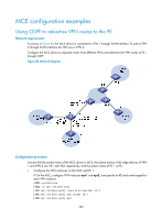
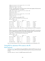
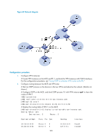
[MCE-ospf-10-area-0.0.0.0] network 30.1.1.0 0.0.0.255 [MCE-ospf-10-area-0.0.0.0] quit [MCE-ospf-10] import-route static # On PE 1, start OSPF process 10, bind the process with VPN instance vpn1, set the domain ID to 10, and advertise subnet 30.1.1.0 in area 0. [PE1] ospf 10 router-id 100.100.10.1 vpn-instance vpn1 [PE1-ospf-10] domain-id 10 [PE1-ospf-10] area 0 [PE1-ospf-10-area-0.0.0.0] network 30.1.1.0 0.0.0.255 [PE1-ospf-10-area-0.0.0.0] quit [PE1-ospf-10] quit # On PE 1, display the routing table of VPN1. [PE1] display ip routing-table vpn-instance vpn1 Routing Tables: vpn1 Destinations : 5 Routes : 5 Destination/Mask Proto Pre Cost NextHop 30.1.1.0/24 Direct 0 0 30.1.1.2 30.1.1.2/32 Direct 0 0 127.0.0.1 127.0.0.0/8 Direct 0 0 127.0.0.1 127.0.0.1/32 Direct 0 0 127.0.0.1 192.168.0.0/24 O_ASE 150 1 30.1.1.1 Interface Vlan30 InLoop0 InLoop0 InLoop0 Vlan30 The output shows that the static route of VPN 1 has been redistributed to the OSPF routing table of PE 1. Take similar procedures to configure OSPF process 20 between MCE and PE 1 and redistribute VPN 2's routing information from RIP into the OSPF routing table of MCE. The following output shows that PE 1 has learned the private route of VPN 2 through OSPF. display ip routing-table vpn-instance vpn2 Routing Tables: vpn2 Destinations : 5 Routes : 5 Destination/Mask Proto Pre Cost NextHop Interface 40.1.1.0/24 Direct 0 0 40.1.1.2 Vlan40 40.1.1.2/32 Direct 0 0 127.0.0.1 InLoop0 127.0.0.0/8 Direct 0 0 127.0.0.1 InLoop0 127.0.0.1/32 Direct 0 0 127.0.0.1 InLoop0 192.168.10.0/24 O_ASE 150 1 40.1.1.1 Vlan40 Now, the routing information of the two VPNs has been redistributed into the routing tables on PE 1. Using BGP to advertise VPN routes to the PE Network requirements As shown in Figure 89, use an Ethernet switch as the MCE device. Advertise the VPN routes in site 1 and site 2 to PE 1, so that a VPN's sites across the MPLS backbone network can communicate with each other normally. Use OSPF in both site 1 and site 2. Use EBGP between the MCE and PE 1. 289
-
 1
1 -
2
-
3
-
4
-
5
-
6
-
7
-
8
-
9
-
10
-
11
-
12
-
13
-
14
-
15
-
16
-
17
-
18
-
19
-
20
-
21
-
22
-
23
-
24
-
25
-
26
-
27
-
28
-
29
-
30
-
31
-
32
-
33
-
34
-
35
-
36
-
37
-
38
-
39
-
40
-
41
-
42
-
43
-
44
-
45
-
46
-
47
-
48
-
49
-
50
-
51
-
52
-
53
-
54
-
55
-
56
-
57
-
58
-
59
-
60
-
61
-
62
-
63
-
64
-
65
-
66
-
67
-
68
-
69
-
70
-
71
-
72
-
73
-
74
-
75
-
76
-
77
-
78
-
79
-
80
-
81
-
82
-
83
-
84
-
85
-
86
-
87
-
88
-
89
-
90
-
91
-
92
-
93
-
94
-
95
-
96
-
97
-
98
-
99
-
100
-
101
-
102
-
103
-
104
-
105
-
106
-
107
-
108
-
109
-
110
-
111
-
112
-
113
-
114
-
115
-
116
-
117
-
118
-
119
-
120
-
121
-
122
-
123
-
124
-
125
-
126
-
127
-
128
-
129
-
130
-
131
-
132
-
133
-
134
-
135
-
136
-
137
-
138
-
139
-
140
-
141
-
142
-
143
-
144
-
145
-
146
-
147
-
148
-
149
-
150
-
151
-
152
-
153
-
154
-
155
-
156
-
157
-
158
-
159
-
160
-
161
-
162
-
163
-
164
-
165
-
166
-
167
-
168
-
169
-
170
-
171
-
172
-
173
-
174
-
175
-
176
-
177
-
178
-
179
-
180
-
181
-
182
-
183
-
184
-
185
-
186
-
187
-
188
-
189
-
190
-
191
-
192
-
193
-
194
-
195
-
196
-
197
-
198
-
199
-
200
-
201
-
202
-
203
-
204
-
205
-
206
-
207
-
208
-
209
-
210
-
211
-
212
-
213
-
214
-
215
-
216
-
217
-
218
-
219
-
220
-
221
-
222
-
223
-
224
-
225
-
226
-
227
-
228
-
229
-
230
-
231
-
232
-
233
-
234
-
235
-
236
-
237
-
238
-
239
-
240
-
241
-
242
-
243
-
244
-
245
-
246
-
247
-
248
-
249
-
250
-
251
-
252
-
253
-
254
-
255
-
256
-
257
-
258
-
259
-
260
-
261
-
262
-
263
-
264
-
265
-
266
-
267
-
268
-
269
-
270
-
271
-
272
-
273
-
274
-
275
-
276
-
277
-
278
-
279
-
280
-
281
-
282
-
283
-
284
-
285
-
286
-
287
-
288
-
289
-
290
-
291
-
292
-
293
-
 294
294 -
 295
295 -
 296
296 -
 297
297 -
 298
298 -
 299
299 -
 300
300 -
 301
301 -
 302
302 -
 303
303 -
 304
304 -
305
-
306
-
307
-
308
-
309
-
310
-
311
-
312
 |
 |