HP 6125G HP 6125G & 6125G/XG Blade Switches Layer 3 - IP Routing Confi - Page 238
Troubleshooting OSPFv3 configuration, No OSPFv3 neighbor relationship established, Symptom, Analysis
 |
View all HP 6125G manuals
Add to My Manuals
Save this manual to your list of manuals |
Page 238 highlights
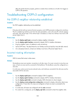
After all switches function properly, perform a master/slave switchover on Switch A to trigger an OSPFv3 GR operation. Troubleshooting OSPFv3 configuration No OSPFv3 neighbor relationship established Symptom No OSPF neighbor relationship can be established. Analysis If the physical link and lower protocol function properly, verify OSPF parameters configured on interfaces. The two neighboring interfaces must have the same parameters, such as the area ID, network segment and mask, and network type. If the network type is broadcast, at least one interface must have a DR priority higher than 0. Process steps 1. Use the display ospfv3 peer command to display neighbor information. 2. Use the display ospfv3 interface command to display OSPFv3 interface information. 3. Ping the neighbor router's IP address to verify connectivity. 4. Verify OSPF timers. The dead interval on an interface must be at least four times the hello interval. 5. On a broadcast network, at least one interface must have a DR priority higher than 0. Incorrect routing information Symptom OSPFv3 cannot find routes to other areas. Analysis The backbone area must maintain connectivity to all other areas. If a router connects to more than one area, at least one area must be connected to the backbone. The backbone cannot be configured as a stub area. In a stub area, routers cannot receive external routes, and interfaces connected to the stub area must be associated with the stub area. Solution 1. Use the display ospfv3 peer command to display OSPFv3 neighbors. 2. Use the display ospfv3 interface command to display OSPFv3 interface information. 3. Use the display ospfv3 lsdb command to display LSDB information to check integrity. 4. Use the display current-configuration configuration command to display information about area configuration. If more than two areas are configured, at least one area is connected to the backbone. 5. In a stub area, all routers are configured with the stub command. 6. If a virtual link is configured, use the display ospf vlink command to check the neighbor state. 228
-
 1
1 -
2
-
3
-
4
-
5
-
6
-
7
-
8
-
9
-
10
-
11
-
12
-
13
-
14
-
15
-
16
-
17
-
18
-
19
-
20
-
21
-
22
-
23
-
24
-
25
-
26
-
27
-
28
-
29
-
30
-
31
-
32
-
33
-
34
-
35
-
36
-
37
-
38
-
39
-
40
-
41
-
42
-
43
-
44
-
45
-
46
-
47
-
48
-
49
-
50
-
51
-
52
-
53
-
54
-
55
-
56
-
57
-
58
-
59
-
60
-
61
-
62
-
63
-
64
-
65
-
66
-
67
-
68
-
69
-
70
-
71
-
72
-
73
-
74
-
75
-
76
-
77
-
78
-
79
-
80
-
81
-
82
-
83
-
84
-
85
-
86
-
87
-
88
-
89
-
90
-
91
-
92
-
93
-
94
-
95
-
96
-
97
-
98
-
99
-
100
-
101
-
102
-
103
-
104
-
105
-
106
-
107
-
108
-
109
-
110
-
111
-
112
-
113
-
114
-
115
-
116
-
117
-
118
-
119
-
120
-
121
-
122
-
123
-
124
-
125
-
126
-
127
-
128
-
129
-
130
-
131
-
132
-
133
-
134
-
135
-
136
-
137
-
138
-
139
-
140
-
141
-
142
-
143
-
144
-
145
-
146
-
147
-
148
-
149
-
150
-
151
-
152
-
153
-
154
-
155
-
156
-
157
-
158
-
159
-
160
-
161
-
162
-
163
-
164
-
165
-
166
-
167
-
168
-
169
-
170
-
171
-
172
-
173
-
174
-
175
-
176
-
177
-
178
-
179
-
180
-
181
-
182
-
183
-
184
-
185
-
186
-
187
-
188
-
189
-
190
-
191
-
192
-
193
-
194
-
195
-
196
-
197
-
198
-
199
-
200
-
201
-
202
-
203
-
204
-
205
-
206
-
207
-
208
-
209
-
210
-
211
-
212
-
213
-
214
-
215
-
216
-
217
-
218
-
219
-
220
-
221
-
222
-
223
-
224
-
225
-
226
-
227
-
228
-
229
-
230
-
231
-
232
-
 233
233 -
 234
234 -
 235
235 -
 236
236 -
 237
237 -
 238
238 -
 239
239 -
 240
240 -
 241
241 -
 242
242 -
 243
243 -
244
-
245
-
246
-
247
-
248
-
249
-
250
-
251
-
252
-
253
-
254
-
255
-
256
-
257
-
258
-
259
-
260
-
261
-
262
-
263
-
264
-
265
-
266
-
267
-
268
-
269
-
270
-
271
-
272
-
273
-
274
-
275
-
276
-
277
-
278
-
279
-
280
-
281
-
282
-
283
-
284
-
285
-
286
-
287
-
288
-
289
-
290
-
291
-
292
-
293
-
294
-
295
-
296
-
297
-
298
-
299
-
300
-
301
-
302
-
303
-
304
-
305
-
306
-
307
-
308
-
309
-
310
-
311
-
312
 |
 |