HP 6125G HP 6125G & 6125G/XG Blade Switches Layer 3 - IP Routing Confi - Page 230
OSPFv3 configuration examples, Configuring OSPFv3 areas, Network requirements, Configuration procedure
 |
View all HP 6125G manuals
Add to My Manuals
Save this manual to your list of manuals |
Page 230 highlights
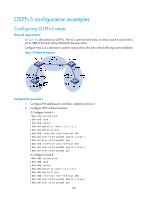
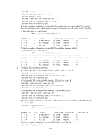
OSPFv3 configuration examples Configuring OSPFv3 areas Network requirements In Figure 78, all switches run OSPFv3. The AS is split into three areas, in which, Switch B and Switch C act as ABRs to forward routing information between areas. Configure Area 2 as a stub area in order to reduce LSAs in the area without affecting route reachability. Figure 78 Network diagram Configuration procedure 1. Configure IPv6 addresses for interfaces. (Details not shown.) 2. Configure OSPFv3 basic functions: # Configure Switch A. system-view [SwitchA] ipv6 [SwitchA] ospfv3 [SwitchA-ospfv3-1] router-id 1.1.1.1 [SwitchA-ospfv3-1] quit [SwitchA] interface vlan-interface 300 [SwitchA-Vlan-interface300] ospfv3 1 area 1 [SwitchA-Vlan-interface300] quit [SwitchA] interface vlan-interface 200 [SwitchA-Vlan-interface200] ospfv3 1 area 1 [SwitchA-Vlan-interface200] quit # Configure Switch B. system-view [SwitchB] ipv6 [SwitchB] ospfv3 [SwitchB-ospfv3-1] router-id 2.2.2.2 [SwitchB-ospfv3-1] quit [SwitchB] interface vlan-interface 100 [SwitchB-Vlan-interface100] ospfv3 1 area 0 [SwitchB-Vlan-interface100] quit 220
-
 1
1 -
2
-
3
-
4
-
5
-
6
-
7
-
8
-
9
-
10
-
11
-
12
-
13
-
14
-
15
-
16
-
17
-
18
-
19
-
20
-
21
-
22
-
23
-
24
-
25
-
26
-
27
-
28
-
29
-
30
-
31
-
32
-
33
-
34
-
35
-
36
-
37
-
38
-
39
-
40
-
41
-
42
-
43
-
44
-
45
-
46
-
47
-
48
-
49
-
50
-
51
-
52
-
53
-
54
-
55
-
56
-
57
-
58
-
59
-
60
-
61
-
62
-
63
-
64
-
65
-
66
-
67
-
68
-
69
-
70
-
71
-
72
-
73
-
74
-
75
-
76
-
77
-
78
-
79
-
80
-
81
-
82
-
83
-
84
-
85
-
86
-
87
-
88
-
89
-
90
-
91
-
92
-
93
-
94
-
95
-
96
-
97
-
98
-
99
-
100
-
101
-
102
-
103
-
104
-
105
-
106
-
107
-
108
-
109
-
110
-
111
-
112
-
113
-
114
-
115
-
116
-
117
-
118
-
119
-
120
-
121
-
122
-
123
-
124
-
125
-
126
-
127
-
128
-
129
-
130
-
131
-
132
-
133
-
134
-
135
-
136
-
137
-
138
-
139
-
140
-
141
-
142
-
143
-
144
-
145
-
146
-
147
-
148
-
149
-
150
-
151
-
152
-
153
-
154
-
155
-
156
-
157
-
158
-
159
-
160
-
161
-
162
-
163
-
164
-
165
-
166
-
167
-
168
-
169
-
170
-
171
-
172
-
173
-
174
-
175
-
176
-
177
-
178
-
179
-
180
-
181
-
182
-
183
-
184
-
185
-
186
-
187
-
188
-
189
-
190
-
191
-
192
-
193
-
194
-
195
-
196
-
197
-
198
-
199
-
200
-
201
-
202
-
203
-
204
-
205
-
206
-
207
-
208
-
209
-
210
-
211
-
212
-
213
-
214
-
215
-
216
-
217
-
218
-
219
-
220
-
221
-
222
-
223
-
224
-
 225
225 -
 226
226 -
 227
227 -
 228
228 -
 229
229 -
 230
230 -
 231
231 -
 232
232 -
 233
233 -
 234
234 -
 235
235 -
236
-
237
-
238
-
239
-
240
-
241
-
242
-
243
-
244
-
245
-
246
-
247
-
248
-
249
-
250
-
251
-
252
-
253
-
254
-
255
-
256
-
257
-
258
-
259
-
260
-
261
-
262
-
263
-
264
-
265
-
266
-
267
-
268
-
269
-
270
-
271
-
272
-
273
-
274
-
275
-
276
-
277
-
278
-
279
-
280
-
281
-
282
-
283
-
284
-
285
-
286
-
287
-
288
-
289
-
290
-
291
-
292
-
293
-
294
-
295
-
296
-
297
-
298
-
299
-
300
-
301
-
302
-
303
-
304
-
305
-
306
-
307
-
308
-
309
-
310
-
311
-
312
 |
 |
