HP 6125G HP 6125G & 6125G/XG Blade Switches Layer 3 - IP Routing Confi - Page 46
Configuring an additional metric for a RIP interface, Network requirements
 |
View all HP 6125G manuals
Add to My Manuals
Save this manual to your list of manuals |
Page 46 highlights
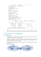
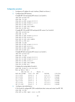
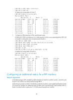
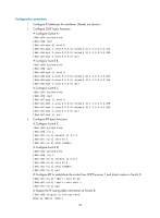
[SwitchB-rip-200] import-route direct [SwitchB-rip-200] quit # Display the routing table of Switch C. [SwitchC] display ip routing-table Routing Tables: Public Destinations : 8 Routes : 8 Destination/Mask Proto Pre Cost NextHop Interface 10.2.1.0/24 RIP 100 1 12.3.1.1 Vlan200 11.1.1.0/24 RIP 100 1 12.3.1.1 Vlan200 12.3.1.0/24 Direct 0 0 12.3.1.2 Vlan200 12.3.1.2/32 Direct 0 0 127.0.0.1 InLoop0 16.4.1.0/24 Direct 0 0 16.4.1.1 Vlan400 16.4.1.1/32 Direct 0 0 127.0.0.1 InLoop0 127.0.0.0/8 Direct 0 0 127.0.0.1 InLoop0 127.0.0.1/32 Direct 0 0 127.0.0.1 InLoop0 4. Configure an filtering policy to filter redistributed routes: # Define ACL 2000 and reference it to a filtering policy to filter routes redistributed from RIP 100 on Switch B, making the route not advertised to Switch C. [SwitchB] acl number 2000 [SwitchB-acl-basic-2000] rule deny source 10.2.1.1 0.0.0.255 [SwitchB-acl-basic-2000] rule permit [SwitchB-acl-basic-2000] quit [SwitchB] rip 200 [SwitchB-rip-200] filter-policy 2000 export rip 100 # Display the routing table of Switch C. [SwitchC] display ip routing-table Routing Tables: Public Destinations : 7 Routes : 7 Destination/Mask Proto Pre Cost NextHop Interface 11.1.1.0/24 RIP 100 1 12.3.1.1 Vlan200 12.3.1.0/24 Direct 0 0 12.3.1.2 Vlan200 12.3.1.2/32 Direct 0 0 127.0.0.1 InLoop0 16.4.1.0/24 Direct 0 0 16.4.1.1 Vlan400 16.4.1.1/32 Direct 0 0 127.0.0.1 InLoop0 127.0.0.0/8 Direct 0 0 127.0.0.1 InLoop0 127.0.0.1/32 Direct 0 0 127.0.0.1 InLoop0 Configuring an additional metric for a RIP interface Network requirements In the following figure, RIP is enabled on all the interfaces of Switch A, Switch B, Switch C, Switch D, and Switch E. The switches are interconnected through RIPv2. Switch A has two links to Switch D. The link from Switch B to Switch D is more stable than that from Switch C to Switch D. Configure an additional metric for RIP routes received through VLAN-interface 200 on Switch A so that Switch A prefers the 1.1.5.0/24 network learned from Switch B. 36
-
 1
1 -
2
-
3
-
4
-
5
-
6
-
7
-
8
-
9
-
10
-
11
-
12
-
13
-
14
-
15
-
16
-
17
-
18
-
19
-
20
-
21
-
22
-
23
-
24
-
25
-
26
-
27
-
28
-
29
-
30
-
31
-
32
-
33
-
34
-
35
-
36
-
37
-
38
-
39
-
40
-
 41
41 -
 42
42 -
 43
43 -
 44
44 -
 45
45 -
 46
46 -
 47
47 -
 48
48 -
 49
49 -
 50
50 -
 51
51 -
52
-
53
-
54
-
55
-
56
-
57
-
58
-
59
-
60
-
61
-
62
-
63
-
64
-
65
-
66
-
67
-
68
-
69
-
70
-
71
-
72
-
73
-
74
-
75
-
76
-
77
-
78
-
79
-
80
-
81
-
82
-
83
-
84
-
85
-
86
-
87
-
88
-
89
-
90
-
91
-
92
-
93
-
94
-
95
-
96
-
97
-
98
-
99
-
100
-
101
-
102
-
103
-
104
-
105
-
106
-
107
-
108
-
109
-
110
-
111
-
112
-
113
-
114
-
115
-
116
-
117
-
118
-
119
-
120
-
121
-
122
-
123
-
124
-
125
-
126
-
127
-
128
-
129
-
130
-
131
-
132
-
133
-
134
-
135
-
136
-
137
-
138
-
139
-
140
-
141
-
142
-
143
-
144
-
145
-
146
-
147
-
148
-
149
-
150
-
151
-
152
-
153
-
154
-
155
-
156
-
157
-
158
-
159
-
160
-
161
-
162
-
163
-
164
-
165
-
166
-
167
-
168
-
169
-
170
-
171
-
172
-
173
-
174
-
175
-
176
-
177
-
178
-
179
-
180
-
181
-
182
-
183
-
184
-
185
-
186
-
187
-
188
-
189
-
190
-
191
-
192
-
193
-
194
-
195
-
196
-
197
-
198
-
199
-
200
-
201
-
202
-
203
-
204
-
205
-
206
-
207
-
208
-
209
-
210
-
211
-
212
-
213
-
214
-
215
-
216
-
217
-
218
-
219
-
220
-
221
-
222
-
223
-
224
-
225
-
226
-
227
-
228
-
229
-
230
-
231
-
232
-
233
-
234
-
235
-
236
-
237
-
238
-
239
-
240
-
241
-
242
-
243
-
244
-
245
-
246
-
247
-
248
-
249
-
250
-
251
-
252
-
253
-
254
-
255
-
256
-
257
-
258
-
259
-
260
-
261
-
262
-
263
-
264
-
265
-
266
-
267
-
268
-
269
-
270
-
271
-
272
-
273
-
274
-
275
-
276
-
277
-
278
-
279
-
280
-
281
-
282
-
283
-
284
-
285
-
286
-
287
-
288
-
289
-
290
-
291
-
292
-
293
-
294
-
295
-
296
-
297
-
298
-
299
-
300
-
301
-
302
-
303
-
304
-
305
-
306
-
307
-
308
-
309
-
310
-
311
-
312
 |
 |