HP 6125G HP 6125G & 6125G/XG Blade Switches Layer 3 - IP Routing Confi - Page 126
Troubleshooting OSPF configuration, No OSPF neighbor relationship established, Symptom, Analysis
 |
View all HP 6125G manuals
Add to My Manuals
Save this manual to your list of manuals |
Page 126 highlights
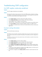
Troubleshooting OSPF configuration No OSPF neighbor relationship established Symptom No OSPF neighbor relationship can be established. Analysis If the physical link and lower layer protocols work well, verify OSPF parameters configured on interfaces. Two neighbors must have the same parameters, such as the area ID, network segment, and mask (a P2P or virtual link may have different network segments and masks). Solution 1. Use the display ospf peer command to display OSPF neighbor information. 2. Use the display ospf interface command to display OSPF interface information. 3. Ping the neighbor router's IP address to verify connectivity. 4. Verify OSPF timers. The dead interval on an interface must be at least four times the hello interval. 5. Use the peer ip-address command to specify the neighbor manually on an NBMA network. 6. On an NBMA or a broadcast network, at least one connected interface must have a router priority higher than 0. Incorrect routing information Symptom OSPF cannot find routes to other areas. Analysis The backbone area must maintain connectivity to all other areas. If a router connects to more than one area, at least one area must be connected to the backbone. The backbone cannot be configured as a stub area. In a Stub area, all routers cannot receive external routes, and all interfaces connected to the stub area must belong to the stub area. Solution 1. Use the display ospf peer command to display neighbors. 2. Use the display ospf interface command to display OSPF interface information. 3. Use the display ospf lsdb command to display the LSDB to verify its integrity. 4. Use the display current-configuration configuration ospf command to display information about area configuration. If more than two areas are configured, at least one area is connected to the backbone. 5. In a stub area, all routers attached are configured with the stub command. In an NSSA area, all routers attached are configured with the nssa command. 6. If a virtual link is configured, use the display ospf vlink command to verify the state of the virtual link. 116
-
 1
1 -
2
-
3
-
4
-
5
-
6
-
7
-
8
-
9
-
10
-
11
-
12
-
13
-
14
-
15
-
16
-
17
-
18
-
19
-
20
-
21
-
22
-
23
-
24
-
25
-
26
-
27
-
28
-
29
-
30
-
31
-
32
-
33
-
34
-
35
-
36
-
37
-
38
-
39
-
40
-
41
-
42
-
43
-
44
-
45
-
46
-
47
-
48
-
49
-
50
-
51
-
52
-
53
-
54
-
55
-
56
-
57
-
58
-
59
-
60
-
61
-
62
-
63
-
64
-
65
-
66
-
67
-
68
-
69
-
70
-
71
-
72
-
73
-
74
-
75
-
76
-
77
-
78
-
79
-
80
-
81
-
82
-
83
-
84
-
85
-
86
-
87
-
88
-
89
-
90
-
91
-
92
-
93
-
94
-
95
-
96
-
97
-
98
-
99
-
100
-
101
-
102
-
103
-
104
-
105
-
106
-
107
-
108
-
109
-
110
-
111
-
112
-
113
-
114
-
115
-
116
-
117
-
118
-
119
-
120
-
 121
121 -
 122
122 -
 123
123 -
 124
124 -
 125
125 -
 126
126 -
 127
127 -
 128
128 -
 129
129 -
 130
130 -
 131
131 -
132
-
133
-
134
-
135
-
136
-
137
-
138
-
139
-
140
-
141
-
142
-
143
-
144
-
145
-
146
-
147
-
148
-
149
-
150
-
151
-
152
-
153
-
154
-
155
-
156
-
157
-
158
-
159
-
160
-
161
-
162
-
163
-
164
-
165
-
166
-
167
-
168
-
169
-
170
-
171
-
172
-
173
-
174
-
175
-
176
-
177
-
178
-
179
-
180
-
181
-
182
-
183
-
184
-
185
-
186
-
187
-
188
-
189
-
190
-
191
-
192
-
193
-
194
-
195
-
196
-
197
-
198
-
199
-
200
-
201
-
202
-
203
-
204
-
205
-
206
-
207
-
208
-
209
-
210
-
211
-
212
-
213
-
214
-
215
-
216
-
217
-
218
-
219
-
220
-
221
-
222
-
223
-
224
-
225
-
226
-
227
-
228
-
229
-
230
-
231
-
232
-
233
-
234
-
235
-
236
-
237
-
238
-
239
-
240
-
241
-
242
-
243
-
244
-
245
-
246
-
247
-
248
-
249
-
250
-
251
-
252
-
253
-
254
-
255
-
256
-
257
-
258
-
259
-
260
-
261
-
262
-
263
-
264
-
265
-
266
-
267
-
268
-
269
-
270
-
271
-
272
-
273
-
274
-
275
-
276
-
277
-
278
-
279
-
280
-
281
-
282
-
283
-
284
-
285
-
286
-
287
-
288
-
289
-
290
-
291
-
292
-
293
-
294
-
295
-
296
-
297
-
298
-
299
-
300
-
301
-
302
-
303
-
304
-
305
-
306
-
307
-
308
-
309
-
310
-
311
-
312
 |
 |