HP 6125G HP 6125G & 6125G/XG Blade Switches Layer 3 - IP Routing Confi - Page 51
Con Switch A.
 |
View all HP 6125G manuals
Add to My Manuals
Save this manual to your list of manuals |
Page 51 highlights
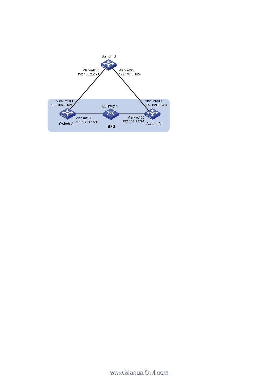
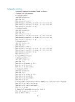
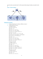
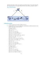
learns the static route sent by Switch C with the output interface being the interface connected to Switch B. Figure 11 Network diagram Configuration procedure 1. Configure IP addresses for interfaces. (Details not shown.) 2. Configure RIP basic functions: # Configure Switch A. system-view [SwitchA] rip 1 [SwitchA-rip-1] version 2 [SwitchA-rip-1] undo summary [SwitchA-rip-1] network 192.168.1.0 [SwitchA-rip-1] quit [SwitchA] interface vlan-interface 100 [SwitchA-Vlan-interface100] rip bfd enable [SwitchA-Vlan-interface100] quit [SwitchA] rip 2 [SwitchA-rip-2] version 2 [SwitchA-rip-2] undo summary [SwitchA-rip-2] network 192.168.2.0 [SwitchA-rip-2] quit # Configure Switch B. system-view [SwitchB] rip 1 [SwitchB-rip-1] version 2 [SwitchB-rip-1] undo summary [SwitchB-rip-1] network 192.168.2.0 [SwitchB-rip-1] network 192.168.3.0 [SwitchB-rip-1] quit # Configure Switch C. system-view [SwitchC] rip 1 [SwitchC-rip-1] version 2 41
-
 1
1 -
2
-
3
-
4
-
5
-
6
-
7
-
8
-
9
-
10
-
11
-
12
-
13
-
14
-
15
-
16
-
17
-
18
-
19
-
20
-
21
-
22
-
23
-
24
-
25
-
26
-
27
-
28
-
29
-
30
-
31
-
32
-
33
-
34
-
35
-
36
-
37
-
38
-
39
-
40
-
41
-
42
-
43
-
44
-
45
-
 46
46 -
 47
47 -
 48
48 -
 49
49 -
 50
50 -
 51
51 -
 52
52 -
 53
53 -
 54
54 -
 55
55 -
 56
56 -
57
-
58
-
59
-
60
-
61
-
62
-
63
-
64
-
65
-
66
-
67
-
68
-
69
-
70
-
71
-
72
-
73
-
74
-
75
-
76
-
77
-
78
-
79
-
80
-
81
-
82
-
83
-
84
-
85
-
86
-
87
-
88
-
89
-
90
-
91
-
92
-
93
-
94
-
95
-
96
-
97
-
98
-
99
-
100
-
101
-
102
-
103
-
104
-
105
-
106
-
107
-
108
-
109
-
110
-
111
-
112
-
113
-
114
-
115
-
116
-
117
-
118
-
119
-
120
-
121
-
122
-
123
-
124
-
125
-
126
-
127
-
128
-
129
-
130
-
131
-
132
-
133
-
134
-
135
-
136
-
137
-
138
-
139
-
140
-
141
-
142
-
143
-
144
-
145
-
146
-
147
-
148
-
149
-
150
-
151
-
152
-
153
-
154
-
155
-
156
-
157
-
158
-
159
-
160
-
161
-
162
-
163
-
164
-
165
-
166
-
167
-
168
-
169
-
170
-
171
-
172
-
173
-
174
-
175
-
176
-
177
-
178
-
179
-
180
-
181
-
182
-
183
-
184
-
185
-
186
-
187
-
188
-
189
-
190
-
191
-
192
-
193
-
194
-
195
-
196
-
197
-
198
-
199
-
200
-
201
-
202
-
203
-
204
-
205
-
206
-
207
-
208
-
209
-
210
-
211
-
212
-
213
-
214
-
215
-
216
-
217
-
218
-
219
-
220
-
221
-
222
-
223
-
224
-
225
-
226
-
227
-
228
-
229
-
230
-
231
-
232
-
233
-
234
-
235
-
236
-
237
-
238
-
239
-
240
-
241
-
242
-
243
-
244
-
245
-
246
-
247
-
248
-
249
-
250
-
251
-
252
-
253
-
254
-
255
-
256
-
257
-
258
-
259
-
260
-
261
-
262
-
263
-
264
-
265
-
266
-
267
-
268
-
269
-
270
-
271
-
272
-
273
-
274
-
275
-
276
-
277
-
278
-
279
-
280
-
281
-
282
-
283
-
284
-
285
-
286
-
287
-
288
-
289
-
290
-
291
-
292
-
293
-
294
-
295
-
296
-
297
-
298
-
299
-
300
-
301
-
302
-
303
-
304
-
305
-
306
-
307
-
308
-
309
-
310
-
311
-
312
 |
 |