HP Color LaserJet CM4730 Service Manual
HP Color LaserJet CM4730 - Multifunction Printer Manual
 |
View all HP Color LaserJet CM4730 manuals
Add to My Manuals
Save this manual to your list of manuals |
HP Color LaserJet CM4730 manual content summary:
- HP Color LaserJet CM4730 | Service Manual - Page 1
HP Color LaserJet CM4730 MFP Service Manual - HP Color LaserJet CM4730 | Service Manual - Page 2
- HP Color LaserJet CM4730 | Service Manual - Page 3
HP Color LaserJet CM4730 MFP Service Manual - HP Color LaserJet CM4730 | Service Manual - Page 4
in this document is subject to change without notice. The only warranties for HP products and services are set forth Windows®, Windows NT®, Windows® XP, and Windows Vista™ are U.S. registered trademarks of the Microsoft Corporation. PANTONE®* *Pantone, Inc.'s checkstandard trademark for color - HP Color LaserJet CM4730 | Service Manual - Page 5
Table of contents 1 Product information Product comparison ...2 HP Color LaserJet CM4730 MFP 2 HP Color LaserJet CM4730f MFP 3 HP Color LaserJet CM4730fsk MFP 3 HP Color LaserJet CM4730fm MFP 4 Product features ...5 Product walkaround ...9 Front view ...9 Back view ...10 Interface ports ...11 - HP Color LaserJet CM4730 | Service Manual - Page 6
44 Supported printer drivers 44 Remove software for Windows 45 Select the correct printer driver 45 Universal printer drivers 45 Driver default gateway 55 Configure TCP/IPv6 parameters 56 Disable network protocols (optional 56 Disable IPX/SPX 56 Disable AppleTalk 57 Disable DLC/LLC 57 HP - HP Color LaserJet CM4730 | Service Manual - Page 7
Print Quality menu ...94 Troubleshooting menu ...96 Resets menu ...100 Service menu ...100 Management tools ...102 Information pages ...102 HP Easy Printer Care software 102 Supported operating systems 102 Open HP Easy Printer Care software 102 HP Easy Printer Care software sections 102 Embedded - HP Color LaserJet CM4730 | Service Manual - Page 8
HP Web Jetadmin software 107 HP Printer Utility for Macintosh 107 Open the HP Printer Utility 107 Print a cleaning page 108 Print a configuration page 108 View supplies status 108 Order supplies online and use other support features 109 Upload a file to the printer 109 Update the firmware - HP Color LaserJet CM4730 | Service Manual - Page 9
128 ADF maintenance kit ...128 Calibrate the Hard disk ...140 CPU ...140 FIH (foreign interface harness 140 MFP memory ...140 Read-only memory 140 Random-access memory 140 DIMM Fuser motor failure detection 147 ETB motor failure detection 147 Rear exhaust fan failure detection 147 Cartridge - HP Color LaserJet CM4730 | Service Manual - Page 10
control 154 Between-sheets temperature control 154 Temperature protective function 154 Protective function by the CPU 154 Protective function by the fuser heater safety 171 Step 8: Fusing 171 Cleaning block ...172 Step 9: Drum cleaning 172 Print cartridges ...172 Memory tag ...174 viii ENWW - HP Color LaserJet CM4730 | Service Manual - Page 11
Cartridge presence detection 174 Memory tag detection 174 Photosensitive drum detection 174 Developing cylinder disengaging Calibration and cleaning 178 ETB cleaning ...179 Color misregistration corrective control 180 Color misregistration detection 181 Image stabilization control 182 - HP Color LaserJet CM4730 | Service Manual - Page 12
212 ADF open jam ...212 2 X 500-sheet paper feeder ...213 Pickup and feed operations 214 2 X 500-sheet jam detection 216 Output devices ...217 IPTU ...217 -stationary jam 223 Residual-media jam 223 Power-on sequence 223 MBM driver ...224 MBM switches and sensors 227 MBM PCBs ...228 MBM list of - HP Color LaserJet CM4730 | Service Manual - Page 13
2, 3, and 4 ...278 ADF input tray ...279 ADF pickup and feed rollers 281 ADF separation pad ...283 ADF delivery guide (clear mylar sheet 285 Face-down tray assembly 287 Fuser ...288 Tray 2, 3, or 4 pickup and feed rollers 289 MP tray pickup roller ...290 Tray 2 separation roller ...292 Tray - HP Color LaserJet CM4730 | Service Manual - Page 14
assembly ...387 Motors and fans ...388 Drum motors ...388 Fuser motor ...389 Fuser pressure release motor 390 Developing disengaging motor 395 Pickup motor assembly ...396 Power supply fan ...397 Cartridge fan ...399 Sub power supply fan ...400 Delivery fan ...402 Control fan 1 ...403 Control - HP Color LaserJet CM4730 | Service Manual - Page 15
hinges ...458 2 X 500-sheet paper input assembly components 460 pickup assembly ...480 Paper feeder door-open switch 483 Paper feeder driver PCB 485 Intermediate paper transfer MBM driver PCB ...509 6 Problem solving Problem-solving process ...512 Problem-solving checklist 512 Problem-solving - HP Color LaserJet CM4730 | Service Manual - Page 16
582 Printout color error 582 Incorrect shade 583 Missing color ...583 Cartridge error 583 Color match error 583 Overhead transparency defects 584 Print quality problems associated with the environment 584 Print quality problems associated with jams 584 Print quality troubleshooting pages 585 - HP Color LaserJet CM4730 | Service Manual - Page 17
Print quality troubleshooting tool 585 Image defect examples ...585 Horizontal lines or streaks 585 Misaligned color 587 Vertical lines ...588 Repetitive defects 589 Color fade in all colors 590 Color fade in one color 591 Fingerprints and media dents 592 Loose toner ...593 Smeared toner 594 - HP Color LaserJet CM4730 | Service Manual - Page 18
Network connectivity problems ...615 Troubleshooting network printing problems 615 Loopback test ...616 Ping test ...616 Functional checks ...617 Engine test ...617 Formatter test ...617 MFP resets ...619 Cold reset ...619 NVRAM initialization ...619 Tools for troubleshooting ...621 Individual - HP Color LaserJet CM4730 | Service Manual - Page 19
support ...665 Supplies and accessories 665 Assembly locations ...670 Major components ...670 External covers and panels ...674 Internal components ...686 ADF components ...730 Scanner components ...752 2 X 500-sheet feeder directly from HP ...816 Order through service or support providers 816 - HP Color LaserJet CM4730 | Service Manual - Page 20
Ozone production ...832 Power consumption ...832 Toner consumption ...832 Paper use ...832 Plastics ...832 HP LaserJet print supplies 832 Return and recycling instructions 833 United States and Puerto Rico 833 Multiple returns (two to eight cartridges 833 Single returns 833 Shipping 833 Non - HP Color LaserJet CM4730 | Service Manual - Page 21
1 Product information ● Product comparison ● Product features ● Product walkaround ● Media specifications ● Information pages ENWW 1 - HP Color LaserJet CM4730 | Service Manual - Page 22
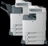
Product comparison HP Color LaserJet CM4730 MFP The HP Color LaserJet CM4730 MFP is the base model, and comes standard with the following items: ● 100-sheet multipurpose input tray (tray 1) ● Three 500-sheet input trays ● Automatic document feeder (ADF) that holds up to 50 pages ● HP Jetdirect - HP Color LaserJet CM4730 | Service Manual - Page 23
HP Color LaserJet CM4730f MFP The HP Color LaserJet CM4730f MFP has the same features as the base model and includes an analog fax accessory. HP Color LaserJet CM4730fsk MFP The HP Color LaserJet CM4730fsk MFP has the same features as the base model and includes the following items: ● Analog fax - HP Color LaserJet CM4730 | Service Manual - Page 24
HP Color LaserJet CM4730fm MFP The HP Color LaserJet CM4730fm MFP has the same features as the base model and includes the following items: ● Analog fax accessory ● Output accessory bridge ● 3-bin mailbox accessory 4 Chapter 1 Product information ENWW - HP Color LaserJet CM4730 | Service Manual - Page 25
duplexing) Color digital sending Color access data to use RAM more efficiently User interface ● HP Easy Select Control Panel ● An embedded Web server to gain access to support and order supplies (for network-connected products) ● HP Easy Printer Care software (a Web-based status and troubleshooting - HP Color LaserJet CM4730 | Service Manual - Page 26
pages at 5% coverage ● No-shake cartridge design ● Authentic HP print cartridge detection ● Automatic toner-strip remover Paper-handling ● Input ● Tray 1 (multipurpose tray): A multipurpose tray for paper, transparencies, labels, and envelopes. Holds up to 100 sheets of paper or 20 envelopes. ● Tray - HP Color LaserJet CM4730 | Service Manual - Page 27
Optional stapler/stacker (standard on the CM4730fm MFP): The stapler/stacker staples up to a 30-sheet document and stacks up to 500 sheets. ● Optional 3-bin mailbox (standard on the CM4730fsk MFP): One bin stacks up to 500 sheets, and two bins stack up to 100 sheets each for a total capacity of 700 - HP Color LaserJet CM4730 | Service Manual - Page 28
● Group PIN authentication (Group 1 and Group 2) ● User PIN authentication 8 Chapter 1 Product information ENWW - HP Color LaserJet CM4730 | Service Manual - Page 29
1 ADF top cover 2 Automatic document feeder (ADF) input tray for copy/scan/fax originals 3 Control-panel status lights 4 Control-panel display with touchscreen functionality 5 Control-panel keypad 6 Right-side covers (provides access to the print cartridges and other consumables) 7 Tray 2, 3, and - HP Color LaserJet CM4730 | Service Manual - Page 30
Back view 1 Output bin 2 Interface ports 3 On/off switch 4 Power connection 10 Chapter 1 Product information ENWW - HP Color LaserJet CM4730 | Service Manual - Page 31
The ports are at the left, rear corner of the MFP. 1 Foreign interface harness (FIH) 2 USB 2.0 3 ACC Kensington lock 8 Network connection (embedded HP Jetdirect print server) 9 AUX port Serial printer. The serial number contains information about the country/region of origin, the printer - HP Color LaserJet CM4730 | Service Manual - Page 32
serial number Figure 1-1 Sample model and serial number label Model name HP Color LaserJet CM4730 MFP HP Color LaserJet CM4730f MFP HP Color LaserJet CM4730fsk MFP HP Color LaserJet CM4730fm MFP Model number CB480A CB481A CB482A CB483A 12 Chapter 1 Product information ENWW - HP Color LaserJet CM4730 | Service Manual - Page 33
might cause the following problems: ● Poor print quality ● Increased jams ● Premature wear on the product, requiring repair For best results, use only HP-brand paper and print media designed for laserjets or multiuse. Do not use paper or print media made for inkjet printers. Hewlett-Packard Company - HP Color LaserJet CM4730 | Service Manual - Page 34
x 250 mm (6.93 x 9.84 in.) 8k 270 x390 mm (10.63 x 15.35 in.) 16k 197 x 273 mm (7.75 x 10.75 in.) Trays 2, 3, 4 Stapler Table 1-2 Supported envelopes and postcards Size Dimensions Envelope #10 105 x 241 mm (4.13 x 9.49 in.) Envelope DL 110 x 220 mm (4.33 x 8.66 in.) Envelope C5 162 x 229 - HP Color LaserJet CM4730 | Service Manual - Page 35
supports printing on special media. Use the following guidelines to obtain satisfactory results. When using special paper or print media, be sure to set the type and size in your print driver to obtain the best print results. CAUTION: HP LaserJet printers use fusers to bond dry toner , windows, or - HP Color LaserJet CM4730 | Service Manual - Page 36
table provides the instructions for printing the to print the page from the MFP control panel 1. From the Home HP Jetdirect print server or an optional hard disk drive, additional configuration pages print that provide information about those devices. Supplies status page Shows print-cartridge toner - HP Color LaserJet CM4730 | Service Manual - Page 37
page from the MFP control panel Contains Dial List 5. Touch Print. For more information, see the fax guide that came with the device. Font lists 1. From the Home screen 2. Touch Information. 3. Touch Sample Pages/Fonts. 4. Touch either PCL Font List or PS Font List. 5. Touch Print. NOTE: - HP Color LaserJet CM4730 | Service Manual - Page 38
18 Chapter 1 Product information ENWW - HP Color LaserJet CM4730 | Service Manual - Page 39
● Installation checklist ● Unpacking the MFP ● Connecting power ● Installing print cartridges ● Installing a new control panel overlay ● Install memory and print server cards ● Test the MFP operation ● Sleep and wake ● Connecting to a computer or network ● Printer software ● Network configuration - HP Color LaserJet CM4730 | Service Manual - Page 40
and service. Verify that surface has adequate, level support. Ensure the MFP is on a level and stable surface. Ensure wheel locks are engaged. Verify that all orange tape and packaging materials have been removed. See details in the HP Color LaserJet CM4730 MFP series Getting Started Guide - HP Color LaserJet CM4730 | Service Manual - Page 41
Table 2-1 HP Color LaserJet CM4730 MFP installation (continued) Item Details ● All optional devices from the copier glass of the MFP. Place configuration page face down on copier glass and press Start. Verify you can copy from the Automatic Document Feeder (ADF). Place configuration page face - HP Color LaserJet CM4730 | Service Manual - Page 42
HP Color LaserJet CM4730 MFP weighs approximately 124 kg (273 lb). HP recommends having three or more people move or position the MFP. 1. Remove the top of the box and remove the outer cardboard wrapping from the sides of the MFP. Remove the ramps, power supply cord, CD-ROM, and user documentation - HP Color LaserJet CM4730 | Service Manual - Page 43
3. Remove the inner cardboard frame and foam corner packaging, and install the ramps. 4. Remove the shipping blocks and plastic bag that surround the MFP. ENWW Unpacking the MFP 23 - HP Color LaserJet CM4730 | Service Manual - Page 44
into the prepared location. CAUTION: Do not attempt to move the MFP by yourself. At least two people must move the MFP into the prepared location. While two people can move the MFP, using three or four people to unpack and install the MFP is easier and safer. 6. Remove the packing tape from the - HP Color LaserJet CM4730 | Service Manual - Page 45
9. Unlock the scanner. ENWW Unpacking the MFP 25 - HP Color LaserJet CM4730 | Service Manual - Page 46
Connecting power 1. Plug the AC power cord into the MFP and into the power outlet. 2. Turn the MFP on. 26 Chapter 2 Installation ENWW - HP Color LaserJet CM4730 | Service Manual - Page 47
Open the covers on the right side of the MFP. CAUTION: The fuser might be hot. 2. Grasp the green handle and pull down the ETB. CAUTION: Do not place any item on the transfer belt while it is open. If the belt is punctured, print quality problems could result. ENWW Installing print cartridges 27 - HP Color LaserJet CM4730 | Service Manual - Page 48
box in which the new cartridge arrived. See the enclosed recycling guide for recycling instructions. 8. If a non-HP print cartridge was installed, check the product control panel for further instructions. For additional help, go to http://www.hp.com/support/ljcm4730mfp. 28 Chapter 2 Installation - HP Color LaserJet CM4730 | Service Manual - Page 49
may be used from the one that is installed. Overlays are available for several languages. If setting up an MFP for a language other than English, follow this procedure. 1. Turn the MFP off. 2. Remove the backing from the adhesive side of the overlay. 3. Position the new overlay over the top of - HP Color LaserJet CM4730 | Service Manual - Page 50
graphics or PS documents, or if you use many downloaded fonts. Additional memory also allows the MFP to print multiple collated copies at the maximum speed. NOTE: Single in-line memory modules (SIMMs) / dual in-line memory modules (DIMMs) used on previous HP LaserJet printers are not compatible - HP Color LaserJet CM4730 | Service Manual - Page 51
Device Settings tab, click Printer Memory (in the Installable Options section). 4. Select the total amount of memory that is now installed. 5. Click OK. Install an HP Jetdirect or EIO print server card The HP Color LaserJet CM4730 MFP is equipped with an embedded HP Jetdirect print server port. If - HP Color LaserJet CM4730 | Service Manual - Page 52
2. Disconnect all power and interface cables. 3. Locate an open EIO slot. Loosen and remove the two retaining screws holding the cover for the EIO slot, and then remove the cover. You will not need these screws and the cover again. They can be discarded. 32 Chapter 2 Installation ENWW - HP Color LaserJet CM4730 | Service Manual - Page 53
4. Firmly insert the HP Jetdirect print server card into the EIO slot. 5. Insert and tighten the retaining screws that came with the print server card. 6. Connect the network cable. ENWW Install memory and print server cards 33 - HP Color LaserJet CM4730 | Service Manual - Page 54
turn the MFP on. 8. Print a configuration page. In addition to an MFP configuration page and a Supplies Status page, an HP Jetdirect configuration correct port. See the computer or operating system documentation for instructions. ● Reinstall the software, choosing the network installation this time - HP Color LaserJet CM4730 | Service Manual - Page 55
Test the MFP operation Print a configuration page to ensure that the MFP is working correctly. See Information pages on page 16 for instructions. ENWW Test the MFP operation 35 - HP Color LaserJet CM4730 | Service Manual - Page 56
Sleep and wake Set the sleep delay Use the sleep-delay feature to set the period of time that the MFP must be idle before it enters the sleep mode. The default setting is 30 minutes. 1. Scroll to and touch Administration. 2. Touch Time/Scheduling. 3. Touch Sleep Delay. 4. Touch the sleep-delay - HP Color LaserJet CM4730 | Service Manual - Page 57
Parallel port 6 EIO interface expansion slot 7 Kensington lock 8 Network connection (embedded HP Jetdirect print server) 9 Accessory port Parallel connection Establish a parallel connection by connecting the MFP to the computer with a bidirectional parallel cable (IEEE-1284C compliant) that - HP Color LaserJet CM4730 | Service Manual - Page 58
the bidirectional parallel interface, ensure that the most recent printer driver is installed. Factory settings support automatic switching between the parallel port and one or more network connections on the MFP. USB connection This MFP supports USB 2.0 device connections. The USB ports are located - HP Color LaserJet CM4730 | Service Manual - Page 59
Figure 2-2 USB connection 1 USB connector 2 USB port Auxiliary connection This MFP supports an auxiliary connection for paper-handling input devices. The port is located on the back of the MFP. NOTE: This connector cannot be used by the 3-bin mailbox or stapler/stacker accessories. ENWW Connecting - HP Color LaserJet CM4730 | Service Manual - Page 60
MFP, HP Color LaserJet CM4730fsk MFP, and HP Color LaserJet CM4730fm MFP models are equipped with an HP LaserJet analog fax accessory already installed. Windows users can also install the optional HP Digital Sending Software (HP DSS), which provides digital faxing services. For complete instructions - HP Color LaserJet CM4730 | Service Manual - Page 61
Follow these instructions to connect the fax accessory to a phone jack. 1. Locate the phone cord that is included with the fax accessory kit. Connect one end for information about troubleshooting problems with the fax accessory, see the HP LaserJet Analog Fax Accessory 300 User Guide provided with - HP Color LaserJet CM4730 | Service Manual - Page 62
Software for Windows Supported Windows versions Software Windows Installer PCL 5 driver software1 PCL 6 driver software (black only) PCL 6 driver software PostScript emulation HP Easy Printer Care1 HP Web Jetadmin1 Universal Print Driver 1 Available only on the World Wide Web. Windows 2000R/XPR - HP Color LaserJet CM4730 | Service Manual - Page 63
OK. 3. When prompted, click Install and follow the instructions on the computer screen. 4. Click Finish when the installation MFP CD or go to http://www.hp.com/support/ljcm4730mfp for help or more information. Install Windows printing-system software for networks The software on the MFP CD supports - HP Color LaserJet CM4730 | Service Manual - Page 64
, check the installation notes and readme files on the MFP CD or the flyer that came in the MFP box, or go to http://www.hp.com/support/ ljcm4730mfp. Supported printer drivers Operating system Windows Mac OS X V10.2 and later PCL 5 PCL 6 PS level 3 emulation 44 Chapter 2 Installation ENWW - HP Color LaserJet CM4730 | Service Manual - Page 65
and allow the computer to communicate with the MFP by using a printer language. ● HP PCL 5 driver. Recommended for general office Windows monochrome and color printing. Backward compatible with previous PCL versions or older LaserJet printers. Best choice for third-party/custom solutions (forms - HP Color LaserJet CM4730 | Service Manual - Page 66
time of installation. Some accessories that the Driver Autoconfiguration supports are the duplexing unit, optional paper trays, and dual inline memory modules (DIMMs). 46 Chapter 2 Installation ENWW - HP Color LaserJet CM4730 | Service Manual - Page 67
Properties in the Print dialog box to open the printer driver. Settings changed in the Printer Properties dialog box do not override settings anywhere else in the printing software. ● Default printer driver settings: The default printer driver settings determine the settings used in all print jobs - HP Color LaserJet CM4730 | Service Manual - Page 68
Open the printer drivers Operating System To change the settings for all print jobs until the software program is closed To change the default settings for all print jobs To change the device configuration settings Windows 2000, XP, 1. On the File menu in the 1. Click Start, click Settings, 1. - HP Color LaserJet CM4730 | Service Manual - Page 69
HP Printer Utility is supported for Mac OSX V10.2 or later. Install software for Macintosh Install Macintosh software for direct connections (USB) NOTE: Macintosh computers do not support parallel port connections. The Apple PostScript driver HP LaserJet Installer folder. 4. Follow the instructions - HP Color LaserJet CM4730 | Service Manual - Page 70
icon on the desktop. 3. Double-click the Installer icon in the HP LaserJet Installer folder. 4. Follow the instructions on the computer screen. 5. On the computer hard drive, open Applications, open Utilities, and then open Print Center or Printer Setup Utility. NOTE: If you are using Mac OS X V10 - HP Color LaserJet CM4730 | Service Manual - Page 71
, visit www.hp.com/go/webjetadmin. When installed on a host server, a Windows client can gain access to HP Web Jetadmin by using a supported Web browser (such as Microsoft® Internet Explorer 4.x or Netscape Navigator 4.x or later) by navigating to the HP Web Jetadmin host. ENWW Printer software 51 - HP Color LaserJet CM4730 | Service Manual - Page 72
device that anyone who has a networkconnected computer and a standard Web browser can use. No special software is installed or configured, but you must have a supported Web browser on your computer. To gain access to the embedded Web server, type the IP address for the device in the address line of - HP Color LaserJet CM4730 | Service Manual - Page 73
Shopping online for supplies ● Using HP online troubleshooting and maintenance tools You can use the HP Easy Printer Care software when the device is directly connected to your computer or a network running Windows. Macintosh is not supported. To download the HP Easy Printer Care software, go to www - HP Color LaserJet CM4730 | Service Manual - Page 74
or HP LaserJet Utility for Macintosh) NOTE: For more information about using the embedded Web server, see Embedded Web server on page 104 For more information on supported networks and network configuration tools, see the HP Jetdirect Print Server Administrator's Guide. The guide comes with printers - HP Color LaserJet CM4730 | Service Manual - Page 75
touch Initial Setup. 3. Touch Networking and I/O. 4. Touch Embedded Jetdirect. 5. Touch TCP/IP. 6. Touch IPV4 Settings. 7. Touch Config Method. 8. Touch Manual. 9. Touch Save. 10. Touch Manual Settings. 11. Touch Subnet Mask. 12. Touch the Subnet Mask text box. 13. Use the touchscreen keypad to type - HP Color LaserJet CM4730 | Service Manual - Page 76
see the HP Jetdirect Print Server Administrator's Guide. Disable network protocols (optional) By factory default, all supported network protocols IPX/SPX NOTE: Do not disable this protocol in Windows-based systems that print to the printer through IPX/SPX. 1. Scroll to and touch Administration. - HP Color LaserJet CM4730 | Service Manual - Page 77
print server model. For available HP Jetdirect EIO print server models, go to http://www.hp.com/go/jetdirect. NOTE: Configure the card through the control panel, the printer installation software, or HP Web Jetadmin. Refer to the HP Jetdirect print server documentation for more information. ENWW - HP Color LaserJet CM4730 | Service Manual - Page 78
to the embedded Web server so that unauthorized users cannot change the MFP settings. 1. Open the embedded Web server by typing the IP address. 2. Click the Settings tab. 3. On the left side of the window, click Security. 4. Type the password next to New Password, and type it again next to Verify - HP Color LaserJet CM4730 | Service Manual - Page 79
disabled, try using the default PIN that is listed to disable it. For assistance, use the HP Instant Support service, which is available through the embedded Web server or at http://instantsupport.hp.com. Secure Disk Erase To protect deleted data from unauthorized access on the MFP hard drive, use - HP Color LaserJet CM4730 | Service Manual - Page 80
MFP cleans up temporary data for jobs after the erase mode has been changed. Gaining access to Secure Disk Erase Use HP about the HP Secure Disk Erase feature, see the HP support flyer or go to http://www.hp.com/go users to type a user identification and a password before they can use any of the DSS - HP Color LaserJet CM4730 | Service Manual - Page 81
6. Type a Device Password. 7. In the Control Panel Access section, select Maximum Lock. This Kensington locking accessory for the formatter cage on an HP Color LaserJet CM4730 MFP, please contact HP at http://www.hp.com/ support/ljcm4730mfp. The following figure indicates where the lock should - HP Color LaserJet CM4730 | Service Manual - Page 82
and input devices Optional paper-handling devices are available for the MFP. ● 3-bin mailbox with output accessory bridge ● Stapler/stacker with output accessory bridge Each of these accessories comes with an installation guide that explains how to install it. After installing an accessory, print - HP Color LaserJet CM4730 | Service Manual - Page 83
● Management tools ● Approximate replacement intervals for supplies ● ETB life under different circumstances ● Managing print cartridges ● Replacing supplies ● Using the cleaning page ● Clean the MFP ● Performing preventive maintenance ● Calibrate the scanner ● Set the real-time clock ENWW 63 - HP Color LaserJet CM4730 | Service Manual - Page 84
message on the touchscreen. 2 Data light The Data light indicates that the device is receiving data. 3 Ready light The Ready the device, press the Sleep button. 8 Reset button Resets the job settings to factory or user-defined default values. 9 Stop button Stops the active job - HP Color LaserJet CM4730 | Service Manual - Page 85
of the device if you have signed in for access to restricted features. After you sign out, the device restores all options to the default settings. Touch Network Address to find information about the network connection. The current date and time appear here. The system administrator can select the - HP Color LaserJet CM4730 | Service Manual - Page 86
you of an error or warning, touch the error ( ) or warning ( ) button to open a message that describes the problem. The message also contains instructions to help solve the problem. Navigate the Administration menu From the Home screen, touch Administration to open the menu structure. You might need - HP Color LaserJet CM4730 | Service Manual - Page 87
Status Page Print Shows the status of supplies such as cartridges, maintenance kits, and staples. Usage Page Print Shows information about that are installed in this device. Color Usage Job Log Print A directory page that contains job-by-job color usage information. Page content includes the - HP Color LaserJet CM4730 | Service Manual - Page 88
(default) MFP. RGB Samples Print Printout of color samples for different RGB values. The samples act as a guide for color matching. CMYK Samples Print Printout of color samples for different CMYK values. The samples act as a guide for color matching. PCL Font List Print A list of printer - HP Color LaserJet CM4730 | Service Manual - Page 89
originals. Select Portrait if the short edge is at the top or select Landscape if the long edge is at the top. Optimize Text/Picture Manually Adjust Text Printed Picture Photograph Optimize the output for a particular type of original: text, pictures, or a mixture of both. If you select - HP Color LaserJet CM4730 | Service Manual - Page 90
Image adjustment Administration > Default Job Options > Image Adjustment Table 3-3 Image Adjustment menu Menu Removal setting to remove faint images from the background or to remove a light background color. Sharpness Adjust the value within the range. Adjust the Sharpness setting to clarify or - HP Color LaserJet CM4730 | Service Manual - Page 91
of copies for a copy job. Number of Sides 1 Set the default number of sides for copies. 2 Color/Black Color (default) Black Choose whether the default copy mode is color or black. Auto Include Margins Off (default) On This feature automatically reduces the image size during scanning so the - HP Color LaserJet CM4730 | Service Manual - Page 92
Fax Options Table 3-5 Fax Send menu Menu item Sub-menu item Values Description Resolution Standard (100x200dpi) (default) Fine (200x200dpi) Superfine (300x300dpi) Set the resolution for sent documents. Higher resolution images have more dots per inch (dpi), so they show more detail. Lower - HP Color LaserJet CM4730 | Service Manual - Page 93
> Default E-mail Options Menu item Document File Type Output Quality Resolution Color/Black TIFF Version Values PDF (default) JPEG TIFF M-TIFF High (large file) Medium (default) Low (small file) 300 DPI 200 DPI 150 DPI (default) 75 DPI Color scan (default) Black/white scan TIFF 6.0 (default) TIFF - HP Color LaserJet CM4730 | Service Manual - Page 94
Folder Options Menu item Color/Black Document File Type TIFF version Output Quality Resolution Values Color scan Black/white scan (default) PDF (default) M-TIFF TIFF JPEG TIFF 6.0 (default) TIFF (post 6.0) High (large file) Medium (default) Low (small file) 75 DPI 150 DPI (default) 200 DPI 300 DPI - HP Color LaserJet CM4730 | Service Manual - Page 95
Description Copies Per Job Type a value. Set the default number of copies for print jobs. Default Paper Size (List of supported sizes) Select a paper size. Default Custom Paper Size Unit of measure Millimeters Inches Configure the default paper size that is used when the user selects - HP Color LaserJet CM4730 | Service Manual - Page 96
-menu item Month Day Year Hour Minute AM PM Values YYYY/MMM/DD (default) MMM/DD/YYYY DD/MMM/YYYY Description Use this feature to set the format that are used to time-stamp outgoing faxes. 12 hour (AM/PM) (default) 24 hour 1 Minute 20 minutes Use this feature to select the time interval that - HP Color LaserJet CM4730 | Service Manual - Page 97
manage any jobs that are stored on the device. Quick Copy Job Held Timeout Off 1 Hour 4 Hours 1 Day 1 Week Sleep mode Disable Use Sleep Delay (default) Use this feature to customize the sleep mode settings for this device. Select Use Sleep Delay to set the device to enter sleep mode after - HP Color LaserJet CM4730 | Service Manual - Page 98
HP Easy Printer Care, or Web Jetadmin. This item allows the administrator to disable or restrict color copying. This item controls how the engine switches from color mode to monochrome mode for maximum performance and print cartridge life. Choose Auto to reset the MFP to the factory default setting - HP Color LaserJet CM4730 | Service Manual - Page 99
(default) Enabled (default) Disabled Description I/O timeout refers to the elapsed time before a print job fails. If the stream of data that used to identify the device. This name is listed on the HP Jetdirect configuration page. The default host name is NPIxxxxxx, where xxxxxx is the last six - HP Color LaserJet CM4730 | Service Manual - Page 100
HP Jetdirect devices. This menu appears if Config Method was set to DHCP and a DHCP lease for the print server exists. No (default Manual) Configure parameters directly from the printer control panel: IP Address: The unique IP address of the printer TCP print data connection is closed (default is 270 - HP Color LaserJet CM4730 | Service Manual - Page 101
this item and choose On to enable manual configuration, or Off to disable manual configuration. Address: Use this item to type to contact your Independent Service Provider (ISP) for the proxy server address. Type the port number used by the proxy server for client support. The port number identifies - HP Color LaserJet CM4730 | Service Manual - Page 102
. On (default): Enable the DLC/LLC protocol. Yes (default): Prints a page that contains the current security settings on the HP Jetdirect print settings are reset to factory defaults. This menu provides tests to help diagnose network hardware or TCP/IP network connection problems. Embedded tests - HP Color LaserJet CM4730 | Service Manual - Page 103
No to not choose it. This test helps to identify data path and corruption problems on an HP postscript level 3 emulation device. It sends a predefined PS test results. Select Yes to print results. If you select No (default), results are not printed. Specify whether to initiate the ping test. Select - HP Color LaserJet CM4730 | Service Manual - Page 104
data with current results. Select Yes to update the data, or No to maintain the existing data. However, a refresh automatically occurs when the menu times out or you manually the hub/ switch port. (A 1000T half-duplex selection is not supported.) 10T Half: 10 Mbps, half-duplex operation. 10T Full: 10 - HP Color LaserJet CM4730 | Service Manual - Page 105
Table 3-11 Jetdirect menus (continued) Menu item Sub-menu item Sub-menu item Print Protocols Values and Description 100TX Full: 100 Mbps, full-duplex operation. 100TX Auto: Limits auto-negotiation to a maximum link speed of 100 Mbps. 1000TX Full: 1000 Mbps, full-duplex operation. Use this item - HP Color LaserJet CM4730 | Service Manual - Page 106
Information Phone Number Company Name Values (Countries/regions listed) Description Configure the settings that are legally required for outgoing faxes. Disabled Enabled (default) Use this feature to enable or disable PC Fax Send. PC Fax Send enables users to send faxes through the device from - HP Color LaserJet CM4730 | Service Manual - Page 107
tool for troubleshooting fax problems. Default (default) Custom This setting should be left at the default value and only changed when directed by an HP technical support agent. Adjustment procedures associated with this setting are beyond the scope of this guide. Default (default) Custom This - HP Color LaserJet CM4730 | Service Manual - Page 108
when directed by an HP technical support agent. Default (default) Custom This setting should be left at the default value and only changed when directed by an HP technical support agent. Adjustment procedures associated with this setting are beyond the scope of this guide. Off Set the volume - HP Color LaserJet CM4730 | Service Manual - Page 109
MFP Enter a value (IP Address). Allow Transfer to New DSS Off On (default) Allow Use of Digital Send Service Off On (default) Fax Number Confirmation Disable (default a scanned document to a network folder. This feature allows you to configure the device for use with an HP Digital Sending - HP Color LaserJet CM4730 | Service Manual - Page 110
between any activity on the control panel and the device resetting to the default settings. On Job (default) Set the amount of time that a clearable warning appears on the control panel. Auto continue (10 seconds) (default) Configure the device behavior when the device encounters certain errors - HP Color LaserJet CM4730 | Service Manual - Page 111
does not match the specified tray and the device pulls from the multipurpose tray instead. Enabled (default) Disabled Select either the PostScript (PS) or HP paper-handling model. Enabled (default) Disabled Turn on or off the control-panel prompt to select another tray when the specified tray - HP Color LaserJet CM4730 | Service Manual - Page 112
Alternative Letterhead Mode Values Enabled (default) Disabled Enabled Disabled (default) Enabled Disabled (default) No early warm up (default) Early warm up No (default) Yes Description Turn on no-wait scanning. With Scan Ahead enabled, the pages in the original document are scanned to disk and - HP Color LaserJet CM4730 | Service Manual - Page 113
default) Enabled Disabled (default) Regular (default) Dark Enabled Disabled (default) Enabled Disabled (default) Enabled Disabled (default) Auto (default) PCL is printed when the device encounters a PDF error. Select the printer language that the device should use. Normally, you should not change - HP Color LaserJet CM4730 | Service Manual - Page 114
default is 60 lines. PCL is a set of printer commands that Hewlett-Packard developed to provide access to printer features. Portrait (default page is blank. Standard (default) Classic Select and maintain input trays by number when you are not using the device driver, or when the software program - HP Color LaserJet CM4730 | Service Manual - Page 115
Sub-menu item Adjust Color Highlights Midtones Shadows Set -20 to 20 along the X or Y axes. 0 is the default. Print a test page for setting the registration. Select the source input device scans across the page from side to side as the sheet feeds from top to bottom into the device. The scan - HP Color LaserJet CM4730 | Service Manual - Page 116
CACO3 Values Color REt Calibration/ default) Disabled Enabled Disabled (default) 1000 (default toner off the pressure roller in the fuser. The process takes up to 2.5 minutes. Performs partial MFP calibrations. Performs all MFP calibrations. Troubleshooting menu Administration > Troubleshooting - HP Color LaserJet CM4730 | Service Manual - Page 117
Troubleshooting Fax T.30 Trace Print T.30 Report When to Print Report Fax Transmit Signal Loss Fax V.34 Fax Speaker Mode Paper Path Sensors Diagnostic Page Disable Cartridge documents. Print Print various diagnostic pages that help solve print-quality problems. Never auto print (default) - HP Color LaserJet CM4730 | Service Manual - Page 118
Table 3-17 Troubleshooting menu (continued) Menu item Sub-menu item Sub-menu bins or only to a specific bin. Standard Output Bin Off (default) On Select whether the duplexer should be included in the test. Range: 2-30, Default=2 Select how many pages should be sent from the specified source - HP Color LaserJet CM4730 | Service Manual - Page 119
Table 3-17 Troubleshooting menu (continued) Menu item Sub-menu item Sub-menu item Finishing Paper Path Test Staples Finishing Options Media Size Media Type Copies Duplex Stack Test Page Media Size Media Type Copies Manual Sensor Test Component Test Duplex Test Page Values Description - HP Color LaserJet CM4730 | Service Manual - Page 120
defaults. Clear Document Feeder Message Clear Use this feature to clear the Order Document Feeder Kit and Replace Document Feeder Kit warning messages. Reset Supplies New Document Feeder Kit (Yes/ Notify the device that a new document-feeder kit has been installed. No) Service menu The Service - HP Color LaserJet CM4730 | Service Manual - Page 121
Count Mono Engine Cycle Count Color Engine Cycle Count Document Feeder Kit Count Document Feeder Kit Interval ADF count Flatbed Count ADF Simplex Count ADF Duplex Count Copy Scan Count Send Scan Count Copy Pages Count Scanner Settings Serial Number Service ID Cold Reset Paper Media Sensor Value - HP Color LaserJet CM4730 | Service Manual - Page 122
associated with the link. For more information on HP Easy Printer Care software, visit http://www.hp.com/go/easyprintercare. Supported operating systems The HP Easy Printer Care software is supported for Windows 2000 and Windows XP. Open HP Easy Printer Care software Use one of the following methods - HP Color LaserJet CM4730 | Service Manual - Page 123
attention. ● Provides links to troubleshooting information and tools. ● Provides links to the HP Web site for registration, support, and for ordering supplies. NOTE: If you use a dial-up connection and did not connect to the Internet when you first opened the HP Easy Printer Care software, you must - HP Color LaserJet CM4730 | Service Manual - Page 124
the embedded Web server, see the Embedded Web Server User Guide, which is on the HP Color LaserJet CM4730 MFP series software CD. Open the embedded Web server To open the embedded Web server, type the IP address or host name of the MFP in a supported Web browser. If you do not know the IP address - HP Color LaserJet CM4730 | Service Manual - Page 125
the Web, and send it to the MFP to be printed. The document must be a print-ready document, such as a .PS, .PDF, .PCL, or .TXT file. Settings tab Use this tab to configure the MFP from your computer. The Settings tab can be password protected. If this MFP is networked, always consult with the system - HP Color LaserJet CM4730 | Service Manual - Page 126
to configure the digital-sending features. NOTE: If the MFP is configured to use the optional HP Digital Sending Software, the options on these tabs are not sending defaults such as the default page-size and the default settings-reset delay. You can also configure these settings by using the MFP - HP Color LaserJet CM4730 | Service Manual - Page 127
supplies such as print cartridges and media. ● Product Support. Connects to the support site for the HP Color LaserJet CM4730 MFP series. HP Web Jetadmin software HP Web Jetadmin is a Web-based software solution for remotely installing, monitoring, and troubleshooting network-connected peripherals - HP Color LaserJet CM4730 | Service Manual - Page 128
printer is not printing jobs at the expected quality level. 1. Open the HP Printer Utility. 2. In the Configuration Settings list, select Color printer supplies (such as print cartridges, imaging drum, or print media) from a computer. 1. Open the HP Printer online, click Order HP Supplies. You must - HP Color LaserJet CM4730 | Service Manual - Page 129
a .PS or .PCL file) is sent, the printer prints the file. 1. Open the HP Printer Utility. 2. In firmware Update the printer firmware by loading the new firmware file from the computer. You can find new firmware files for your printer at http://www.hp.com/support/ljcm4730mfp. 1. Open the HP Printer - HP Color LaserJet CM4730 | Service Manual - Page 130
● To delete a stored job, select a stored job in the list, and then click Delete. Configure trays Change the default printer tray settings from the computer. 1. Open the HP Printer Utility. 2. In the Configuration Settings list, select Tray Configuration. 3. In the Trays list, select the tray to be - HP Color LaserJet CM4730 | Service Manual - Page 131
certain events that occur with the printer, such as a low toner level in a print cartridge. 1. Open the HP Printer Utility. 2. In the Configuration URLs to which you want the e-mail alerts sent. NOTE: If your printer supports e-mail lists, you can make alerts lists for specific events the same - HP Color LaserJet CM4730 | Service Manual - Page 132
Cartridge 12,000 pages1 3 months 3 months Image transfer kit Replace Transfer Kit 120,000 pages2 40 months Image fuser kit Replace Fuser Kit 150,000 pages 50 months Stapler cartridge Replace Stapler Cartridge 5000 pages ADF maintenance kit Replace Document Feeder 90000 pages Kit - HP Color LaserJet CM4730 | Service Manual - Page 133
workload, the customer will need to replace the ETB once or twice in the life of the MFP. In order to help plan supplies purchases, the HP Color LaserJet CM4730 MFP calculates an estimated remaining number of pages that can be printed with the ETB. The number of pages the ETB can print is a function - HP Color LaserJet CM4730 | Service Manual - Page 134
cartridge when the MFP control panel displays a Replace Cartridge message. The control panel display will also indicate the color that should be replaced (if a genuine HP cartridge is currently installed). Replacement instructions are included in the print-cartridge box. CAUTION: If toner - HP Color LaserJet CM4730 | Service Manual - Page 135
cartridge depends on the amount of toner that print jobs require and the length of life for the components inside the cartridge. When printing text at approximately 5% coverage (typical for a business letter), the HP print cartridge address for the MFP home page. This goes to the MFP status page. 2. - HP Color LaserJet CM4730 | Service Manual - Page 136
instructions on installing supplies, see the installation guides provided with each supply item or see more information at http://www.hp.com/support/ljcm4730mfp. When you connect, select Solve a Problem. CAUTION: Hewlett-Packard recommends the use of genuine HP products in this MFP. Use of non-HP - HP Color LaserJet CM4730 | Service Manual - Page 137
and lower covers. Supplies ordering information is also available from the embedded Web server. Replacing the fuser Replace the fuser when a Replace Fuser Kit message appears on the product control panel display. 1. Turn the MFP off. 2. Open the right upper cover. 3. Grasp the purple handles on the - HP Color LaserJet CM4730 | Service Manual - Page 138
5. Install the new fuser. 6. Close the right upper cover. Supplies ordering information is also available from the embedded Web server. Replacing the stapler cartridge The stapler cartridge contains 5,000 staples. Replace the stapler cartridge if the MFP control panel display prompts users with a - HP Color LaserJet CM4730 | Service Manual - Page 139
4. Insert the new staple cartridge into the stapler unit and push down on the green handle until the unit snaps into place. 5. Close the staple cartridge cover, and slide the stapler/stacker into the MFP. ENWW Replacing supplies 119 - HP Color LaserJet CM4730 | Service Manual - Page 140
Using the cleaning page During printing, toner and dust particles can accumulate inside the MFP. Over time, this buildup can cause print quality problems, such as toner specks or smearing. This MFP has a cleaning mode that can correct and prevent these problems. Process a cleaning page 1. From the - HP Color LaserJet CM4730 | Service Manual - Page 141
To maintain print quality, clean the MFP thoroughly every time you replace the print cartridge and whenever print-quality problems occur. WARNING! Avoid touching the fusing area when cleaning the MFP. It can be hot. CAUTION: To avoid permanent damage to the print cartridge, do not use ammonia-based - HP Color LaserJet CM4730 | Service Manual - Page 142
Cleaning the ADF delivery system Clean the ADF only if it is visibly marked or dirty, or if you are experiencing a decrease in copy quality (such as streaking). Clean the ADF delivery system 1. Open the scanner lid. 2. Locate the white, vinyl ADF backing. 3. Clean the ADF backing by wiping them - HP Color LaserJet CM4730 | Service Manual - Page 143
originals, and you notice dust on the rollers. Cleaning the rollers frequently could introduce dust into the device. 1. Open the scanner lid. ENWW Clean the MFP 123 - HP Color LaserJet CM4730 | Service Manual - Page 144
2. Locate the rollers near the white vinyl ADF backing. 3. Wipe the rollers gently with a clean, water-dampened, lint-free cloth. CAUTION: Do not pour water directly onto the rollers. Doing so might damage the device. 4. Close the scanner lid. 124 Chapter 3 Manage and maintain ENWW - HP Color LaserJet CM4730 | Service Manual - Page 145
5. Pull the release lever to open the ADF cover. 6. Locate the rollers. 7. Wipe the rollers with a clean, water-dampened, lint-free cloth. CAUTION: Do not pour water directly onto the rollers. Doing so might damage the device. ENWW Clean the MFP 125 - HP Color LaserJet CM4730 | Service Manual - Page 146
8. Locate the separation pad. 9. Wipe the pad with a clean, water-dampened, lint-free cloth. 10. Close the ADF cover. Clean the mylar strip Clean the mylar strips on the underside of the scanner lid only if you are experiencing a decrease in copy quality (such as vertical lines) when copying using - HP Color LaserJet CM4730 | Service Manual - Page 147
Locate the mylar strip (1). NOTE: Replacement mylar strips are stored in an envelope (2) that is underneath the white vinyl ADF backing. Follow the instructions that are in the envelope. 3. Clean the mylar strip with a clean, damp, lint-free cloth. 4. Close the scanner lid. ENWW Clean the MFP 127 - HP Color LaserJet CM4730 | Service Manual - Page 148
the instructions that come with the kit to install it. After replacing the kit, reset the ADF maintenance kit count. Reset the ADF maintenance kit count 1. Scroll to and touch Administration. 2. Scroll to and touch Resets. 3. Scroll to and touch Reset Supplies. 4. Touch New Document Feeder Kit - HP Color LaserJet CM4730 | Service Manual - Page 149
correct portion of the document is captured. Scanner calibration should be carried out only if you notice offset problems with the scanned images. and adjust the side guides. 2. On the control-panel Home screen, scroll to and touch Administration. 3. Touch Troubleshooting. 4. Touch Calibrate Scanner - HP Color LaserJet CM4730 | Service Manual - Page 150
Set the real-time clock Use the real-time clock feature to set the date and time settings. The date and time information is attached to stored print, fax, and digital-send jobs, so you can identify the most recent versions of stored print jobs. Set the date format 1. On the control panel, scroll to - HP Color LaserJet CM4730 | Service Manual - Page 151
5. Touch the appropriate options to set the correct hour, minute, and AM/PM setting. 6. Touch Save. ENWW Set the real-time clock 131 - HP Color LaserJet CM4730 | Service Manual - Page 152
132 Chapter 3 Manage and maintain ENWW - HP Color LaserJet CM4730 | Service Manual - Page 153
provides information about the following topics: ● Basic operation ● Formatter system ● Engine control system ● Laser/scanner system ● Image formation system ● Pickup/feed system ● Scanner system ● 2 X 500-sheet paper feeder ● Output devices ENWW 133 - HP Color LaserJet CM4730 | Service Manual - Page 154
Basic operation The HP Color LaserJet CM4730 MFP functions are divided into the following systems: ● Engine control system ● Laser/scanner system ● Image formation system ● Pickup/feed system ● Scanner system ● 2 X 500-sheet paper feeder ● Output devices The engine control system controls the laser/ - HP Color LaserJet CM4730 | Service Manual - Page 155
on the drum surface and to clean the ETB. During this period, the MFP checks the toner level and detects whether the cartridges are present. The MFP also executes the pulse width modulation adjustment, color registration adjustment, and image density calibration control as required. STBY (standby - HP Color LaserJet CM4730 | Service Manual - Page 156
a request for a scan. The scanner fan turns on, the scan start position is adjusted, the MFP performs the scan, and data is sent to the formatter. Power on sequence The power on sequence initializes the MFP and checks for possible malfunctions or paper jams. Figure 4-2 Power on sequence on page 137 - HP Color LaserJet CM4730 | Service Manual - Page 157
Disengage developing roller Environment detection Motors initial drive Cartridge presence check Residual paper check Scanner initial position Shift home position Drum phase adjustment Toner level detection ETB cleaning Color misregistration correction Image stabilization control Standby Figure - HP Color LaserJet CM4730 | Service Manual - Page 158
data from the various MFP interfaces ● Monitoring control panel inputs and relaying MFP reserved for firmware), hard driver VIDEO signals M laser driver VIDEO signals C laser driver VIDEO signals Y laser driver Figure 4-3 Formatter system Sleep mode This feature conserves power after the MFP - HP Color LaserJet CM4730 | Service Manual - Page 159
Advanced Functions item. The default setting, ON, allows for two-way parallel communications. The OFF mode disables the advanced functionality. The I/O is compatible with the bidirectional parallel interface standard. USB 2.0 connector The HP Color LaserJet CM4730 MFP supports a USB 2.0 connector on - HP Color LaserJet CM4730 | Service Manual - Page 160
The HP LaserJet CM4730 MFP formatter data is sent to the print engine. Memory capacity can be increased by adding DIMMs to the formatter. Note that adding memory (DIMMs) might also increase the print speed for complex graphics. DIMM slots The DIMM slots can be used to add memory, fonts, or firmware - HP Color LaserJet CM4730 | Service Manual - Page 161
printer command language (PCL). With standard cabling, PJL allows the MFP to perform the following functions: ● Two-way communication with the host computer through a bidirectional parallel connection. The MFP allows the MFP to be configured with a host on each I/O. The MFP can receive data from more - HP Color LaserJet CM4730 | Service Manual - Page 162
the brain of the HP Color LaserJet CM4730 MFP. It controls all Figure 4-4 Engine control system NOTE: In this manual, the abbreviation "PCB" stands for "printed circuit starts to control MFP operations. 4. The MFP enters the standby period. 5. Based on the print command and the image data input from - HP Color LaserJet CM4730 | Service Manual - Page 163
Figure 4-5 DC controller PCB ENWW Engine control system 143 - HP Color LaserJet CM4730 | Service Manual - Page 164
. It controls the MFP engine sequence, ASIC, fuser, pickup motor and driver ASIC. Controls each motor in response to commands from the CPU. ● Reset IC. Monitors voltage and resets the CPU and ASIC when the power is turned on. ● EEPROM. Stores backup data. Motors, fans, and environment sensor The MFP - HP Color LaserJet CM4730 | Service Manual - Page 165
+ , - . / 0 +* 3 Figure 4-6 Motors and fans ENWW 1 2 Engine control system 145 - HP Color LaserJet CM4730 | Service Manual - Page 166
DC motor FAN2: Cartridge fan Exhausts heat around the fuser and cartridges DC motor FAN3: Delivery fan Exhausts heat around fuser DC motor and DC motor Environment sensor Detects the temperature and NA humidity levels inside the MFP Failure detection Yes Yes No Yes No No No Yes Yes Yes Yes - HP Color LaserJet CM4730 | Service Manual - Page 167
in the same manner for each color separately. ● Drum motor start-up fuser motor drive start. ● Fuser motor rotation abnormality. The interval of the fuser Cartridge fan failure detection The DC controller detects a cartridge fan failure and notifies the formatter of an error status when the cartridge - HP Color LaserJet CM4730 | Service Manual - Page 168
. The low voltage power supply unit consists of the following circuits: ● Fuser control circuit. Controls the fuser heater temperature in the fuser. ● Low-voltage power supply circuit. Generates the DC power required in the MFP. Figure 4-7 Low-voltage power supply circuits on page 149 shows each - HP Color LaserJet CM4730 | Service Manual - Page 169
Figure 4-7 Low-voltage power supply circuits Fuser control circuit This MFP uses a ceramic heating method to heat the fuser. Figure 4-8 Fuser power supply circuit on page 149 shows the configuration of the fuser power supply. Figure 4-8 Fuser power supply circuit ENWW Engine control system 149 - HP Color LaserJet CM4730 | Service Manual - Page 170
and between-sheets temperature. It contacts the inside surface of the fuser sleeve at the center and detects the fuser sleeve 180°C (356°F) 1/2 Bond ~ 195°C (383°F) Full Recycled ~ 195°C (383°F) Full Color ~ 195°C (383°F) Full Light ~ 175°C (347°F) Full Intermediate ~ 180°C (356°F) - HP Color LaserJet CM4730 | Service Manual - Page 171
Table 4-3 Fuser temperatures (continued) Media Temperature Tough paper ~ 180°C (356°F) Envelopes ~ 180°C (356°F) Engine speed 1/3 1/2 Low-voltage power supply circuit The low-voltage power supply circuit converts - HP Color LaserJet CM4730 | Service Manual - Page 172
Sleep mode. Power supply recognition The low-voltage power supply circuit recognizes the voltage specification (100V or 200V) that the MFP uses and the CPU switches the temperature control firmware for the fuser accordingly. The CPU monitors the 100V POWER SUPPLY DETECTION signal (PS100V). When the - HP Color LaserJet CM4730 | Service Manual - Page 173
(TH1) and the sub thermistor (TH2). The main thermistor controls the print temperature and the between-sheets temperature. The sub thermistor detects the one-sided temperature rise of the fuser heater, and controls the initial rotation temperature and the start-up temperature. The CPU (IC1101) on - HP Color LaserJet CM4730 | Service Manual - Page 174
of prints when continuous printing. The targeted temperature varies depending on the media types. Between-sheets temperature control This control maintains the temperature of the fuser heater below its normally targeted temperature during continuous printing. This prevents the excessive temperature - HP Color LaserJet CM4730 | Service Manual - Page 175
30° higher than the thermoswitch, as the thermoswitch is not contact with the fuser heater. Temperature failure detection The CPU determines the fuser failure, stops the MFP engine, and notifies the formatter of an fuser failure when it encounters the following conditions: Start-up failure (warm-up - HP Color LaserJet CM4730 | Service Manual - Page 176
● If the detected temperature of the main thermistor is kept 120°C (248°F) or lower for 0.5 seconds continuously, from when the media reaches the fuser until the heater is turned off during the print period. ● If the detected temperature of sub thermistor is kept 50°C (122°F) or lower for 0.5 - HP Color LaserJet CM4730 | Service Manual - Page 177
PRI2, PRI3, PRI4) to the primary charging rollers in each cartridge at the specified timing. The value of the primary charging bias varies is generated to adhere toner to an electrostatic latent image formed on the photosensitive drum. This bias is generated for each color. The high-voltage power - HP Color LaserJet CM4730 | Service Manual - Page 178
roller in the between-sheets during continuous printing. ● Cleaning bias: This bias cleans the ETB by returning any toner remaining on the ETB surface to the photosensitive drum. The transfer rollers in the yellow and magenta cartridges (first and third colors) are applied with DC negative - HP Color LaserJet CM4730 | Service Manual - Page 179
controller when the MFP engine and the data for one page are ready. 3. The DC controller drives the scanner motor and sends the HORIZONTAL SYNCHRONOUS signals to the formatter after receiving the print command. 4. The printer controls each color's laser driver circuit and turns - HP Color LaserJet CM4730 | Service Manual - Page 180
and transferred onto paper in this order: Y (yellow), C (cyan), M (magenta), and K (black). 8. The toner is fused to the paper in the fuser and the paper is delivered to the delivery tray. Printing continues if the DC controller receives another print command from the formatter during the printing - HP Color LaserJet CM4730 | Service Manual - Page 181
according to video signals sent from the formatter. The main components of each laser/scanner assembly are the laser driver, scanner motor, mirrors, and focusing lenses. Each color has its own laser/scanner assembly unit, which is controlled by the DC controller. Figure 4-13 Laser/scanner assembly - HP Color LaserJet CM4730 | Service Manual - Page 182
speed, a latent image is formed the drum. Laser control The laser control circuit allows the laser driver IC to turn the laser diodes LD1 and LD2 on and off according to the image data signals sent by the DC controller. The DC controller sends video signals (VDODAT11, /VDODAT11, VDODAT12, and - HP Color LaserJet CM4730 | Service Manual - Page 183
Figure 4-14 Laser control circuit block diagram The laser control circuit manages the following control and detection functions: ● Laser emission control. Allows the laser diodes to turn on and off according to the video signals sent by the formatter. ● Automatic power control (APC). Allows the - HP Color LaserJet CM4730 | Service Manual - Page 184
(/SCNACC1) or deceleration signal (/SCNDEC1) to the scanner motor driver based on the detected rotational speed. Figure 4-15 Scanner motor constant speed. ● Phase control. Prevents color misregistration by eliminating rotational variations in each color's scanner motor and adjusts the phase of - HP Color LaserJet CM4730 | Service Manual - Page 185
Image formation system The image formation system is the central hub of the MFP. It also forms the toner image on the media. The image formation system consists of four cartridges, the ETB, and the fuser, which are controlled by the DC controller. Figure 4-16 Image formation system on page 165 shows - HP Color LaserJet CM4730 | Service Manual - Page 186
latent image on the photosensitive drum surface visible by applying toner. Step 4: Development 3. Transfer block. Transfers toner image on the photosensitive drum onto the media. Step 5: Attraction Step 6: Transfer NOTE: Toner is transferred onto a sheet of media in the order of yellow (Y), cyan - HP Color LaserJet CM4730 | Service Manual - Page 187
Figure 4-17 Image formation process ENWW Image formation system 167 - HP Color LaserJet CM4730 | Service Manual - Page 188
Electrostatic latent image formation block The image formation process begins in the electrostatic latent image formation block. This block consists of three steps that results in forming an electrostatic latent image on the photosensitive drum: ● Pre-exposure ● Primary charging ● Laser beam - HP Color LaserJet CM4730 | Service Manual - Page 189
surface of the photosensitive drum to create a visible image. This MFP uses a contact development method that keeps the developing cylinder in contact with the drum, pushing the toner against the drum surface for development. The toner is nonmagnetic and consists of resins. Step 4: Development In - HP Color LaserJet CM4730 | Service Manual - Page 190
this step. This process is repeated for each color as the ETB carries the media from the bottom cartridge to the top (C, Y, M, K). In full-color printing, as four colors of toner are piled up on the media, the holding force of the toner weakens as the transfer process progresses. To counteract - HP Color LaserJet CM4730 | Service Manual - Page 191
to the media, making a permanent image that cannot be smeared. This block consists of one step: fusing. Step 8: Fusing This MFP uses the ceramic heater with lower heat capacity to fuse the toner to the media. This method warms up quickly and does not require the power supply during standby period - HP Color LaserJet CM4730 | Service Manual - Page 192
The cleaning blade scrapes off the leftover toner on the drum surface. The residual (waste) toner is collected in the waste toner container by the waste toner feed plate. Print cartridges The MFP has four different print cartridges, one for each color. However, they share the same structure, shown - HP Color LaserJet CM4730 | Service Manual - Page 193
DEVELOPING ALIENATION MOTOR CONTROL signal DEVELOPING ALIENATION signal LED DRIVE signal TONER LEVEL signal Cartridge data DRUM MOTOR DRIVE signal Toner level PCB DC controller PCB Memory controller PCB Memory tag Developing alienation sensor SR11 M8 Developing alienation block Developing - HP Color LaserJet CM4730 | Service Manual - Page 194
that is built into the print cartridge. It stores information about the amount of toner in the cartridge and estimates the remaining life. Figure data DC controller PCB Memory controller PCB Cartridge Figure 4-26 Memory tag The DC controller reads information from the memory tag whenever the MFP - HP Color LaserJet CM4730 | Service Manual - Page 195
Cartridge presence > Figure 4-27 Photosensitive drum detection < Cartridge cartridges, and monochrome print, the developing alienation cam rotates. Accordingly, the rear bottom of the cartridge Only the developing cylinders in the color cartridges (C, Y, M) are disengaged in stops the printer engine, - HP Color LaserJet CM4730 | Service Manual - Page 196
are driven by the belt rotation. During the printing operation, the picked up media is conveyed between the ETB and the photosensitive drum. Simultaneously the toner image is transferred onto the media. The ETB is also 176 Chapter 4 Theory of operation ENWW - HP Color LaserJet CM4730 | Service Manual - Page 197
misregistration and image stabilization control. The pattern image for the color misregistration or image density determination is transferred onto the ETB. rollers (Y, M, C) from the photosensitive drums so that only black toner is transferred onto the ETB during monochrome printing. The ETB motor ( - HP Color LaserJet CM4730 | Service Manual - Page 198
DRIVE signal Bk cartridge M cartridge SL3 M7 Transfer roller engaging cam C cartridge Y cartridge Transfer roller Transfer cleaning. Table 4-4 Calibration timing and duration on page 178 shows when the MFP calibrates, the duration of the calibration, and the type of calibration that occurs - HP Color LaserJet CM4730 | Service Manual - Page 199
toner particles that remain on the ETB are returned to the photosensitive drums in each print cartridge. Figure 4-30 ETB cleaning on page 180 illustrates this step. This control is performed by the DC controller under the following conditions: ● The power is turned on ● During operation of the color - HP Color LaserJet CM4730 | Service Manual - Page 200
in the toner container from transferring onto the ETB. Color misregistration corrective control This control corrects a color misregistration caused by the variation inherent in the laser/scanner unit and each cartridge. The color misregistration corrective control corrects the horizontal scanning - HP Color LaserJet CM4730 | Service Manual - Page 201
direction is corrected at printer engine side by the DC controller controlling the speed of the scanner motor. NOTE: Horizontal magnification is the size of the image in the horizontal direction. Every color has its own photosensitive drum in each cartridge in this MFP. The positions of each - HP Color LaserJet CM4730 | Service Manual - Page 202
formatter of each error when the following errors are found during the color misregistration detection. The initial value is reset to the new color misregistration correction value whenever an error occurs. ● Color misregistration sensor abnormality warning: The light receiver does not receive light - HP Color LaserJet CM4730 | Service Manual - Page 203
controller in the form of the temperature detection signal (TEMSNS) and the humidity detection signal (HUMSNS). The DC controller monitors the environmental conditions of the MFP based on these two signals. ENWW Image formation system 183 - HP Color LaserJet CM4730 | Service Manual - Page 204
thermistor is below 50ºC (122ºF) when the MFP is turned on. ● The door is closed after a print cartridge or ETB is replaced. ● A set number color-registration detection unit measures the image density of these patterns. Image data is returned to the formatter. 3. The formatter uses the image data - HP Color LaserJet CM4730 | Service Manual - Page 205
, it zeros the density data and notifies the formatter. ● Image density sensor abnormality warning: detected ETB surface density is improper. ● Failed image density detection warning: detected density is improper. DC controller PCB Color misregistration pattern image ETB Color misregistration sensor - HP Color LaserJet CM4730 | Service Manual - Page 206
up and feed media. This MFP has four pickup sources: the MP tray, tray 2, and the two trays of the 2 X 500-sheet paper feeder. The primary delivery source is ten motors: pickup motor, ETB motor, four drum motors, fuser motor, fuser pressure release motor, reversing motor, and lifter motor. There - HP Color LaserJet CM4730 | Service Manual - Page 207
Figure 4-34 Pickup/feed system (1 of 2) ENWW Pickup/feed system 187 - HP Color LaserJet CM4730 | Service Manual - Page 208
and solenoids: ● M1: Yellow (Y) drum motor ● M2: Cyan (C) drum motor ● M3: Magenta (M) drum motor ● M4: Black (K) drum motor ● M5: Fuser motor ● M6: Fuser pressure release motor ● M7: ETB motor ● M9: Pickup motor ● M10: Lifter motor ● M8001: Reversing motor ● SL1: Multipurpose tray pickup solenoid - HP Color LaserJet CM4730 | Service Manual - Page 209
4-35 Pickup/feed system (2 of 2) The pickup/feed system consists of the following sensors and switches: ● SR1: Fuser paper sensor ● SR2: Delivery tray paper full sensor ● SR3: Fuser pressure release sensor ● SR4: Multipurpose tray paper sensor ● SR9: Cassette paper sensor ● SR10: Paper stack surface - HP Color LaserJet CM4730 | Service Manual - Page 210
can be divided into three units: ● Pickup/feed unit. From the point the media is picked from the tray until it reaches the fuser. ● Fuser/delivery unit. From the fuser to the face-down tray or other output device. ● Duplex feed unit. From the duplexing reverse inlet unit to the registration roller - HP Color LaserJet CM4730 | Service Manual - Page 211
separation roller (paper separation pad for the MP tray) and a single sheet is fed to the registration roller. 5. The skew of the media is Toner is transferred to the media on the ETB, and the media is fed to the fuser/delivery block. Cassette detection and cassette media size detection The MFP - HP Color LaserJet CM4730 | Service Manual - Page 212
rotates, the pickup arm goes down and the rotating cassette pickup roller touches the media surface. The media in the cassette is fed into the MFP one sheet at a time. 3. The pickup cam rotation allows the pickup arm to go up and the cassette pickup roller disengages from the media surface. 4. The - HP Color LaserJet CM4730 | Service Manual - Page 213
Initial lift The initial lift begins when the cassette is installed in the MFP and the lifting plate remains in the bottom of the cassette. The is also available for the 2 X 500-sheet paper feeders. The initial lift for the cassette and paper feeders does not occur at the same time because of - HP Color LaserJet CM4730 | Service Manual - Page 214
, transmitted through the torque limiter. If a multiple feed occurs, the second paper is pushed back to the cassette and only one sheet is fed into the MFP. Normally, the cassette paper separation roller is imparted with a rotational force in the same direction to the cassette feed roller. However - HP Color LaserJet CM4730 | Service Manual - Page 215
limiter Normally Multiple-feed Figure 4-39 Media lifting Skew correction The skew correction mechanism compensates for the skew of feeding media. This MFP uses the registration shutter method to avoid decreasing throughput. 1. When the media is fed to the registration roller, the leading edge of - HP Color LaserJet CM4730 | Service Manual - Page 216
Skew correction on page 196 illustrates this process. Registration shutter 1) Front side of printer Front side of printer Registration shutter Paper 2) Paper 3) Figure 4-40 Skew correction Media detection This MFP detects the media types to select the optimum print mode automatically. The DC - HP Color LaserJet CM4730 | Service Manual - Page 217
by the receiver. Accordingly, the DC controller identifies the media type: either plain paper, thin paper, thick paper, gloss paper, gloss film, or overhead transparency, and notifies the formatter. Figure 4-41 Media detection on page 197 illustrates this process. DC controller PCB Media sensor LED - HP Color LaserJet CM4730 | Service Manual - Page 218
the media, and then stops the printer engine. ● Automatic mode. When automatic mode is selected, the MFP starts the printing operation in the sheets in the continuous printing. Fusing and delivery block The fuser/delivery unit is structured with two blocks. One is the fuser block that fuses toner - HP Color LaserJet CM4730 | Service Manual - Page 219
toner onto the media. The media is then delivered from the fuser. 4. The image fusing media sensor (SR1) detects the media delivered from the fuser currently printing from the MFP, and stops the printer engine. When the stack The following problems might occur when the media is fed into the fuser. ● - HP Color LaserJet CM4730 | Service Manual - Page 220
releases the fusing pressure to improve media removal and prevent fusing pressure roller deformation. The DC controller rotates the cam driven by the fuser pressure release motor (M6) at the prescribed timing. The lifting plate is pushed down and the fusing pressure roller is released. The fusing - HP Color LaserJet CM4730 | Service Manual - Page 221
Figure 4-43 Fusing pressure release Duplex feed unit This MFP is equipped with an integrated duplexing unit. The duplexing reverse/duplexing feed unit is structured into two blocks. One is the duplexing reverse block, that - HP Color LaserJet CM4730 | Service Manual - Page 222
of the duplexing unit to the DC controller. The MFP supplies +24VDC to the duplexing unit. The +3.3VDC is generated by +24V DC in the duplexing driver PCB, which works for the component devices such as sensors and ICs. Figure 4-45 Duplexing driver PCB signal flow on page 202 shows the signal flow - HP Color LaserJet CM4730 | Service Manual - Page 223
Figure 4-46 Duplexing feed 1. Media that has been printed on one side passes through the fuser. 2. The DC controller sends the reversing command to the duplexing driver at the specified time after the top of page sensor (SR12) detects the leading edge of paper. The prescribed time is when the media - HP Color LaserJet CM4730 | Service Manual - Page 224
command to the duplexing driver after the prescribed time from when the fuser paper sensor (SR1) -scanning is determined. Paper Oblique rollers Right guide Figure 4-47 Paper skew correction 7. The three sheets moving at once (all paper sizes print except legal). Jam detection The MFP uses the - HP Color LaserJet CM4730 | Service Manual - Page 225
that a pickup jam has occurred. NOTE: The MFP attempts to pick up the media several times before control panel display. Delivery delay jam If the fuser paper sensor (SR1) does not detect the leading tray 1, IPTU door, or the 2 x 500-sheet paper deck door is opened during printing, the microprocessor - HP Color LaserJet CM4730 | Service Manual - Page 226
of-page sensor (SR12) fails to detect the leading edge of media within the specified period after the duplexing driver receives a duplexing pickup command from the MFP, the microprocessor on the DC controller PCB determines that a duplexing pickup unit jam 1 has occurred. The transport process stops - HP Color LaserJet CM4730 | Service Manual - Page 227
Scanner system The scanner system adds copying and sending functions to the standard MFP printing function. The scanner assembly consists of an automatic document feeder (ADF) and a flatbed scanner glass surface. Original documents that are fed through the ADF are delivered to the ADF output bin, - HP Color LaserJet CM4730 | Service Manual - Page 228
Figure 4-49 Scanner assembly electrical structure Motors and fans The scanner assembly has five motors and two fans. Three of the motors are stepping motors, which drive the components inside the scanner assembly. The remaining two motors are DC motors, which drive the two fans. Name Carriage - HP Color LaserJet CM4730 | Service Manual - Page 229
analog representation of the raster line. If the ADF is being used, the document then advances in the ADF to the next raster line. If the flatbed is advancing and collection process continues to the end of the sheet. The image data is collected on the scanner controller PCB, where it is processed and - HP Color LaserJet CM4730 | Service Manual - Page 230
Figure 4-51 Scan carriage movement ADF feed system Pages from the original document enter the ADF from the ADF input tray. A separation roller and separation pad work together to separate the top sheet from the stack. The page passes through a set of registration rollers and two sets of feed rollers - HP Color LaserJet CM4730 | Service Manual - Page 231
Figure 4-52 ADF paper path and sensors ADF jam detection When the sensors inside the ADF detect a jam, the feed and read motors immediately stop and send a signal to the scanner controller PCB, which notifies the formatter. An ADF Paper Jam message displays on the product control panel display. To - HP Color LaserJet CM4730 | Service Manual - Page 232
Registration sensor jam If the registration sensor does not detect the trailing edge of the media after the leading edge reaches the scan ready position, the scanner controller PCB determines that an ADF paper jam has occurred. Also, when the scanner duplexer is being used, if the registration - HP Color LaserJet CM4730 | Service Manual - Page 233
2 X 500-sheet paper feeder The MFP includes a 500-sheet paper tray (tray 2) and a larger paper deck that contains two 500sheet feeders (trays 3 and 4). The paper path is shown below. Figure 4-53 2 X 500-sheet feeder paper path The paper feeder driver PCB controls the 2 X 500-sheet feeder operation - HP Color LaserJet CM4730 | Service Manual - Page 234
operations The paper pickup and feeding processes for the 2 X 500-sheet feeder are identical to the processes used for tray 2. See Figure 4-54 2 X 500-sheet feeder I/O block diagram on page 214. The Figure 4-55 2 X 500-sheet feeder pickup and feed diagram on page 215 identifies the components of the - HP Color LaserJet CM4730 | Service Manual - Page 235
500-sheet feeder pickup and feed diagram 1. The DC controller receives a print command from the formatter and sends a pickup command to the paper feeder driver. 2. The paper feeder driver rotates the pickup motor (M8101) in the paper feeder, and the feed roller and the paper feeder separation roller - HP Color LaserJet CM4730 | Service Manual - Page 236
-feed prevention, and jam detection for the 2 X 500sheet feeder function in the same manner as the rest of the MFP. NOTE: Paper lifting operation for the 2 X 500-sheet feeder is the same as that of tray 2, except that the paper feeder driver PCB controls this operation instead of the DC controller - HP Color LaserJet CM4730 | Service Manual - Page 237
56 IPTU paper path The IPTU is controlled by the intermediate paper transfer driver PCB (IPTD PCB). The IPTD PCB controls the IPTU sequencing and these commands. The IPTD PCB submits status information to the DC controller. The MFP supplies +24VDC to the IPTU. The +3.3V for IC is generated by - HP Color LaserJet CM4730 | Service Manual - Page 238
DC controller PCB Intermediate paper transfer driver PCB +24V Top of page sensor Delivery sensor SW Door open detection switch M Feed motor 1 M Feed motor 2 Figure 4-57 IPTU PCB flow IPTU transfer operation - HP Color LaserJet CM4730 | Service Manual - Page 239
56:9B6?C QJIMEK +>@ =7 >286 QJIMEK +>@43 ;10-/ ;10-. 7GGF PNKKGP 7GGF PNKKGP 7GGF PNKKGP @?10-/ @?10-. Figure 4-58 IPTU transfer operation 1. The paper, which has completed the fusing - HP Color LaserJet CM4730 | Service Manual - Page 240
determines a jam, it stops the intermediate paper transfer operation and notifies the MFP of the jam. Pickup delay jam The CPU determines a pickup delay jam stacker mode, mailbox mode, and function-separator mode. The MBM-driver PCA controls all functions in the 3-bin mailbox. To deliver media - HP Color LaserJet CM4730 | Service Manual - Page 241
Figure 4-59 3-bin mailbox operation ENWW Output devices 221 - HP Color LaserJet CM4730 | Service Manual - Page 242
Stacker mode When configured for stacker mode, the 3-bin mailbox fills the bottom output bin (bin 3) first and then fills the next highest bin. Figure 4-60 Media flow when using the stacker mode Mailbox mode When configured for mailbox mode, the 3-bin mailbox stacks print media in each bin as - HP Color LaserJet CM4730 | Service Manual - Page 243
does not detect the leading edge of the media within a specific time period after receiving a delivery-notice command, the microprocessor on the MBM-driver PCA determines that a feed-delay jam has occurred. The time interval is longer for face-up delivery than for face-down delivery. Feed-stationary - HP Color LaserJet CM4730 | Service Manual - Page 244
paper check Door open check Standby Figure 4-62 Power-on sequence MBM driver The MBM driver controls the operational sequence of the MBM. When the MFP is turned on and DC power is supplied to the MBM driver, the MBM driver communicates with the formatter to start an operational control. Then the - HP Color LaserJet CM4730 | Service Manual - Page 245
PS1505 Bin#3 full sensor PS1507 MBM driver Motor driver IC1504 CPU IC1501 LED driver Q1507 Q1508 Solenoid driver Q1504 Solenoid driver Q1503 Printer recognition switch SW1501 Printer Reset IC IC1503 Formatter DC controller PCB CAN driver IC1505 +24VA +5V +24VA Regulator IC1502 - HP Color LaserJet CM4730 | Service Manual - Page 246
Table 4-8 MBM driver components (continued) Part Sensors Inlet sensor (PS1501) Bin 1 paper sensor (PS1504) Bin 2 paper sensor (PS1506) Bin-1-full sensor (PS1503) Bin-2-full sensor (PS1505) Bin-3-full sensor (PS1507) Switch Printer-recognition switch (SW1501) Fan Cooling fan (FM1501) - HP Color LaserJet CM4730 | Service Manual - Page 247
MBM switches and sensors PS1503 PS1505 PS1504 PS1506 SW1501 PS1507 PS1501 PS1501 PS1503 PS1504 PS1505 PS1506 PS1507 SW1501 Inlet sensor Bin 1 paper-full sensor Bin 1 paper sensor Bin 2 paper-full sensor Bin 2 paper sensor Bin 3 paper-full sensor Engine connection switch ENWW Output devices - HP Color LaserJet CM4730 | Service Manual - Page 248
MBM PCBs 12 3 1 LED PCB 2 Sensor PCB 3 MBM driver PCB 228 Chapter 4 Theory of operation ENWW - HP Color LaserJet CM4730 | Service Manual - Page 249
MBM list of signals Table 4-9 List of signals for the MBM driver PCB Connector PIN Abbreviation I/O J1501 1 +24VA 2 +24VA 3 PWRON I 4 GND 5 GND 6 CAN-L I/O DRIVE signal (Orange) USER LED DRIVE signal (Green) PRINTER-RECOGNITION SWITCH signal INLET-DETECTION signal BIN3 TRAY PAPER- - HP Color LaserJet CM4730 | Service Manual - Page 250
Table 4-9 List of signals for the MBM driver PCB (continued) Connector PIN Abbreviation I/O Logic J1505 RECORD signal FLASH ROM RECORD signal RESET signal FLASH ROM RECORD signal directed to the delivery tray. The stacker holds up to 500 sheets of paper (75 g/m2 or 20 lb Bond). ● Stapler/ - HP Color LaserJet CM4730 | Service Manual - Page 251
Figure 4-64 Stapler/stacker paper flow Power-on sequence The following diagram shows the operational sequence of the stapler/stacker from power-on to standby mode. ENWW Output devices 231 - HP Color LaserJet CM4730 | Service Manual - Page 252
Figure 4-65 Stapler/stacker power-on sequence Staple mode In this mode, up to 30 sheets are stapled in one set and are then stacked in the delivery tray. 232 Chapter 4 Theory of operation ENWW - HP Color LaserJet CM4730 | Service Manual - Page 253
guide Upper delivery roller Paddle Inlet roller Delivery roller Lower delivery roller PS1301 Delivery tray Figure 4-66 Staple-mode feed operation 4. After a prescribed period of time, the stapler/stacker driver causes the feed motor (M1303) to drive at the same feed speed as the printer - HP Color LaserJet CM4730 | Service Manual - Page 254
from the turn-out position to the waiting position. Jogger guide Belt Waiting position Turn-out position Figure 4-67 Jogger guide (Top view) 6. When the jogger guide is shifted to the waiting position, the stapler/stacker driver rotates M1301 counter-clockwise again to engage the upper and the - HP Color LaserJet CM4730 | Service Manual - Page 255
driver rotates M1301 counter-clockwise again to disengage the upper and the lower disengagement rollers. Jogger guide Upper delivery guide stapler/stacker driver changes its control depending on whether the paper that was fed is the last sheet of the job or not. ● If it is not the last sheet of - HP Color LaserJet CM4730 | Service Manual - Page 256
of the feed motor (M1303). ● If it is not the last sheet of paper, the driver drives the feed motor at the printer speed. ● If it is the last sheet of paper, the driver stops the feed motor. 12. The stapler/stacker driver drives the motors to perform the alignment operation. ● Horizontal alignment - HP Color LaserJet CM4730 | Service Manual - Page 257
Jogger guide Jogger guide Paper Paper Clamp Paddle Waiting position Staple Alignment position Figure 4-72 Staple-mode feed operation (Top view) 13. The stapler/stacker driver performs the staple operation. 14. After the completion of the staple operation, the stapler/stacker driver - HP Color LaserJet CM4730 | Service Manual - Page 258
stapler/stacker driver shifts the jogger guide to the turn-out position. This allows the paper pile on the jogger guide to fall onto the delivery tray. Jogger guide Upper delivery roller Lower delivery PS1301 roller Delivery tray Figure 4-73 Staple-mode feed operation Jogger guide Paper Jogger - HP Color LaserJet CM4730 | Service Manual - Page 259
controls the jogger motor (M1302), which allows the jogger guide to move so it can align the edge of the paper. Staple stacker driver PCB JOGGER MOTOR DRIVE signal M1302 Belt Jogger guide Figure 4-75 Jogger operation Jogger gear The jogger operation is explained in the following procedure - HP Color LaserJet CM4730 | Service Manual - Page 260
the trailing edge of the paper passes the paper-inlet sensor (PS1301) (when the paper covers the entire jogger guide), the stapler/stacker driver rotates M1302 counter-clockwise to move the jogger guide to the aligned position (adjusted to the width of the paper). The edge of the paper is aligned in - HP Color LaserJet CM4730 | Service Manual - Page 261
moves the jogger guide 3 mm out from the aligned position (loosen alignment). The stapler/stacker driver performs the paddle 79 Paddle operation 5. After the completion of the paddle operation, the stapler/stacker driver changes its controls depending on whether the fed paper is the last paper of - HP Color LaserJet CM4730 | Service Manual - Page 262
Print paper Figure 4-80 Jogger operation (Top view) The home position of the jogger guide is monitored by the stapler/stacker driver and the jogger home-position sensor. NOTE: Whether the fed paper is the last sheet of the job or not is determined by the page information sent from the formatter - HP Color LaserJet CM4730 | Service Manual - Page 263
Stapler/Stacker driver PCB JOGGER HOME POSITION signal (JOG-HP) PS1304 Jogger home position detection flag < Jogger the detection, the stapler/stacker driver rotates the jogger motor (M1302) clockwise to detect its home position. It does this even when the jogger guide is already set at the home - HP Color LaserJet CM4730 | Service Manual - Page 264
the paper that was fed is the last sheet of the job or not. ● If it is not the last sheet of paper, the driver changes the feed-motor speed to the printer speed and returns to step 2. ● If it is the last sheet of paper, the driver does not change the feed-motor speed. When - HP Color LaserJet CM4730 | Service Manual - Page 265
the condition of the stapler unit. NOTE: The staple cartridge holds a maximum of 5,000 staples. Stapler/Stacker driver PCB Staple cartridge STAPLE PRESENCE signal (LS) STAPLE READY signal (/READY) STAPLE HOME POSITION signal (/HP) STAPLER MOTOR DRIVE signal Staple Stapler unit PHOI1 PHOI2 PHOI3 - HP Color LaserJet CM4730 | Service Manual - Page 266
counter-clockwise once. If the /HP signal changes from "L" to "H" during the counter-clockwise rotation, the stapler/stacker driver detects a staple jam and notifies the formatter. Self-priming detection The stapler/stacker self-primes when a new staple cartridge is inserted. The stapler/stacker - HP Color LaserJet CM4730 | Service Manual - Page 267
Stapler/stacker switches and sensors PS1304 PS1306 PS1305 PS1303 PS1301 PS1302 SW1301 Figure 4-84 Switches and sensors Table 4-10 Switches and sensors (part 1) SW1301 Door-open switch PS1301 Paper-inlet sensor PS1302 Paper-delivery sensor PS1303 Delivery-roller disengaging sensor - HP Color LaserJet CM4730 | Service Manual - Page 268
rollers (counter-clockwise) Jogger motor (M1302) Shifts the jogger guide (clockwise: open; counterclockwise: close) Feed motor (M1303) Rotates home-position sensor (PS1304) Detects the home position of the jogger guide Paddle home-position sensor (PS1305) Detects the paddle home position - HP Color LaserJet CM4730 | Service Manual - Page 269
Stapler/stacker motors, solenoid, and fan M1302 M1303 SL1301 M1301 FM1301 Figure 4-85 Motors, solenoid, fan Table 4-12 Motors, solenoid, fan M1301 M1302 M1303 SL1301 FM1301 Paddle motor Jogger motor Feed motor Clamp solenoid Cooling fan ENWW Output devices 249 - HP Color LaserJet CM4730 | Service Manual - Page 270
Stapler/stacker PCBs 1 2 Figure 4-86 PCBs Table 4-13 PCBs 1 LED PCB 2 Staple stacker driver PCB 250 Chapter 4 Theory of operation ENWW - HP Color LaserJet CM4730 | Service Manual - Page 271
1 23 8 765 4 Figure 4-87 Cross-sectional view (part 1) Table 4-14 Cross-sectional view (part 1) 1 Jogger guide 2 Paddle 3 Inlet roller 4 Cooling fan 5 Upper delivery roller 6 Lower delivery roller 7 Delivery tray paper-full sensor 8 Paper delivery tray ENWW Output devices 251 - HP Color LaserJet CM4730 | Service Manual - Page 272
Stapler/Stacker driver PCB M1302 M1303 PS1304 Jogger guide Upper delivery roller Lower delivery roller PS1303 M1301 PS1305 PS1302 PS1306 Stamp Paddle Upper delivery guide Inlet roller SL1301 Stapler unit PS1301 Delivery tray Figure 4-88 Cross-sectional view (part 2) 252 Chapter 4 - HP Color LaserJet CM4730 | Service Manual - Page 273
controls the operational sequence of the stapler/stacker. When the MFP is turned on and DC power is supplied to the stapler/stacker driver from the printer, the stapler/stacker driver communicates with the formatter to start operational control. Then the stapler/stacker enters stand-by mode and - HP Color LaserJet CM4730 | Service Manual - Page 274
PS1301 PS1303 PS1304 PS1305 PS1306 Door switch SW1301 Stapler/Stacker driver PCB Motor driver IC1302 Motor driver IC1303 Motor driver IC1309 CPU IC1304 User LED LED Printer DC controller Reset IC IC1305 CAN driver IC1308 +24VA Formatter +24VA +5V Regulator IC1310 Figure 4-89 Stapler - HP Color LaserJet CM4730 | Service Manual - Page 275
of signals Table 4-16 Stapler/stacker driver list of signals Connector PIN Abbreviation I/O J1301 1 +24V I 2 +24V I GND J1302 1 ULED-G O 2 ULED-O O 3 GND 4 NC 5 +5V O 6 GND 7 JOG-HP I J1303 J1304 J1305 J1306 1 +5V O 2 GND 3 IN-SNS I 1 +24V O 2 +24U - HP Color LaserJet CM4730 | Service Manual - Page 276
Table 4-16 Stapler/stacker driver list of signals (continued) Connector PIN Abbreviation I/O Logic J1307 1 H 10 GND 11 FLASH-ACT1 I L J1308 1 +5V O A 2 GND 3 SWNG-HP I H J1309 J1310 J1311 J1312 1 FAMDRV I A 2 /FANLOCk O L 3 GND 1 +5V supply RESET signal FLASH ROM - HP Color LaserJet CM4730 | Service Manual - Page 277
Table 4-16 Stapler/stacker driver list of signals (continued) Connector PIN Abbreviation I/O Logic J1313 1 +5V O A 2 GND 3 PDL-HP I H J1314 4 +5V O A 5 GND 6 FULL I H 1 NC 2 PDL-BND O P 3 PDL-BD O P 4 PDL-AND O P 5 PDL-AD O P Signal name +5V supply - HP Color LaserJet CM4730 | Service Manual - Page 278
258 Chapter 4 Theory of operation ENWW - HP Color LaserJet CM4730 | Service Manual - Page 279
information about the following topics: ● Removal and replacement strategy ● Service approach ● User-replaceable parts ● Covers, doors, and external ● ADF and scanner components ● ADF components ● 2 X 500-sheet paper input assembly components ● Intermediate paper transfer unit (IPTU) ● Stapler - HP Color LaserJet CM4730 | Service Manual - Page 280
can result. Certain functional checks during troubleshooting might require power to be supplied to the MFP. However, all power should be turned off and the MFP should be unplugged when you remove any MFP assemblies or components. Never operate or service the MFP when the protective cover is removed - HP Color LaserJet CM4730 | Service Manual - Page 281
touching an ESD-sensitive component. Ground the MFP chassis before servicing the MFP. After completing service ● Reinstall the print cartridges. CAUTION: Do not transport the MFP while the print cartridges are installed. ● Reconnect all cables to the MFP. ● Replace all of the accessories and load - HP Color LaserJet CM4730 | Service Manual - Page 282
MFP location. NOTE: When you are disassembling the MFP, place the screws into the chassis holes from when the MFP is reassembled. Table 5-1 Common fasteners used in this MFP Drawing and is used to fasten sheet metal or plastic to is used to fasten sheet metal parts to the sheet metal chassis. It - HP Color LaserJet CM4730 | Service Manual - Page 283
to the major system (for example, the host computer, the network or server, or the MFP system). 2. Determine if the problem is located in the accessories, the scanner assembly, or in the MFP engine. 3. Troubleshoot the problem using the procedures in Chapter 6. After a faulty part is located, the - HP Color LaserJet CM4730 | Service Manual - Page 284
pickup assembly ● Trays 2, 3, and 4 ● ADF input tray ● ADF pickup and feed rollers ● ADF separation pad ● ADF delivery guide (clear mylar sheet) ● Face-down tray assembly ● Fuser ● Tray 2, 3, or 4 pickup and feed rollers ● MP tray pickup roller ● Tray 2 separation roller ● Tray 3 or 4 separation - HP Color LaserJet CM4730 | Service Manual - Page 285
Print cartridges 1. Open the right lower cover. Figure 5-1 Remove the print cartridges (1 of 3) ENWW User-replaceable parts 265 - HP Color LaserJet CM4730 | Service Manual - Page 286
2. Open the ETB. Figure 5-2 Remove the print cartridges (2 of 3) 3. Grasp each print cartridge by the blue handles, and remove it from the MFP. Figure 5-3 Remove the print cartridges (3 of 3) 266 Chapter 5 Removal and replacement ENWW - HP Color LaserJet CM4730 | Service Manual - Page 287
into the tabs (callout 1) and twist gently to release the top of the control panel. Lift the control panel upward to release it from the MFP. Figure 5-5 Remove the control panel (1 of 3) ENWW User-replaceable parts 267 - HP Color LaserJet CM4730 | Service Manual - Page 288
3. Disconnect one connector (callout 2). Figure 5-6 Remove the control panel (2 of 3) 4. Grasp the control panel surround and lift it toward you. Figure 5-7 Remove the control panel (3 of 3) 268 Chapter 5 Removal and replacement ENWW - HP Color LaserJet CM4730 | Service Manual - Page 289
Intermediate paper transfer unit (IPTU) 1. Lift the handle on the IPTU. Figure 5-8 Remove the IPTU (1 of 3) 2. Slide the IPTU outward. Figure 5-9 Remove the IPTU (2 of 3) ENWW User-replaceable parts 269 - HP Color LaserJet CM4730 | Service Manual - Page 290
3. Lift the IPTU upward and remove it from the MFP. Figure 5-10 Remove the IPTU (3 of 3) Stapler/stacker 1. Press and hold the release button on the top of the stapler/stacker. Figure 5-11 Remove the stapler/stacker (1 of 5) 270 Chapter 5 Removal and replacement ENWW - HP Color LaserJet CM4730 | Service Manual - Page 291
2. Pull the stapler/stacker outward. Figure 5-12 Remove the stapler/stacker (2 of 5) 3. Disconnect the connector (callout 1) from the MFP. Figure 5-13 Remove the stapler/stacker (3 of 5) ENWW User-replaceable parts 271 - HP Color LaserJet CM4730 | Service Manual - Page 292
4. Lift the stapler/stacker slightly and remove it from the MFP. Figure 5-14 Remove the stapler/stacker (4 of 5) 5. The IPTU remains in place. Figure 5-15 Remove the stapler/stacker (5 of 5) Staple cartridge 1. Press down the release button on the stapler/stacker and pull the assembly outward. See - HP Color LaserJet CM4730 | Service Manual - Page 293
2. Open the staple cartridge cover. Figure 5-16 Replace the staple cartridge (1 of 3) 3. Grasp the green staple cartridge handle and pull the old staple cartridge upward. Figure 5-17 Replace the staple cartridge (2 of 3) ENWW User-replaceable parts 273 - HP Color LaserJet CM4730 | Service Manual - Page 294
and push down on the green handle until the assembly snaps into place. Close the staple cartridge cover, and slide the stapler/stacker into the MFP. Figure 5-18 Replace the staple cartridge (3 of 3) 3-bin mailbox 1. Slide the assembly outward. Figure 5-19 Remove the 3-bin mailbox (1 of 3) 274 - HP Color LaserJet CM4730 | Service Manual - Page 295
2. Disconnect the cable (callout 1). Figure 5-20 Remove the 3-bin mailbox (2 of 3) 3. Lift the 3-bin mailbox, tilt it upward, and pull to remove it from the MFP. Figure 5-21 Remove the 3-bin mailbox (3 of 3) ETB assembly, removing 1. Open the right lower cover. ENWW User-replaceable parts 275 - HP Color LaserJet CM4730 | Service Manual - Page 296
assembly (1 of 4) 3. Depress the blue tabs on the right and left sides of the ETB (callout 2), and then lift the ETB (callout 1) out of the MFP. Figure 5-23 Remove the ETB assembly (2 of 4) 276 Chapter 5 Removal and replacement ENWW - HP Color LaserJet CM4730 | Service Manual - Page 297
4. Detail of right lever (callout 3). Figure 5-24 Remove the ETB assembly (3 of 4) - right lever 5. Detail of left lever (callout 4). Figure 5-25 Remove the ETB assembly (4 of 4) - left lever ENWW User-replaceable parts 277 - HP Color LaserJet CM4730 | Service Manual - Page 298
MP tray pickup assembly 1. Open the MP tray pickup assembly. 2. Press the two metal tabs on either side to unlock the tray. Figure 5-26 Remove the MP tray pickup assembly (1 of 2) 3. Slide the assembly off the rails. Figure 5-27 Remove the MP tray pickup assembly (2 of 2) Trays 2, 3, and 4 1. Open - HP Color LaserJet CM4730 | Service Manual - Page 299
ADF input tray 1. Open the ADF top cover. Figure 5-28 Remove the ADF input tray (1 of 3) 2. Flex the pivot pin (near the control panel) away from the mounting hole in the ADF chassis. Figure 5-29 Remove the ADF input tray (2 of 3) ENWW User-replaceable parts 279 - HP Color LaserJet CM4730 | Service Manual - Page 300
3. Pull the tray away from the pivot pin at the right side of the input tray, and remove the ADF input tray. Figure 5-30 Remove the ADF input tray (3 of 3) TIP: When reinstalling the ADF input tray, insert the rear pin first, as shown in the following photograph. Be sure that the pin goes under the - HP Color LaserJet CM4730 | Service Manual - Page 301
ADF pickup and feed rollers 1. Open the ADF top cover. Figure 5-31 Remove the ADF pickup and feed rollers (1 of 3) 2. Push down on the locking tab (callout 1), and rotate the top of the assembly away from the ADF. Figure 5-32 Remove the ADF pickup and feed rollers (2 of 3) ENWW User-replaceable - HP Color LaserJet CM4730 | Service Manual - Page 302
3. Release the front (gear end) of the roller assembly drive shaft (callout 2), and slide (callout 3) the assembly toward the front of the MFP to remove it. Figure 5-33 Remove the ADF pickup and feed rollers (3 of 3) 282 Chapter 5 Removal and replacement ENWW - HP Color LaserJet CM4730 | Service Manual - Page 303
ADF separation pad 1. Open the ADF top cover. Figure 5-34 Remove the ADF separation pad (1 of 4) 2. Locate the ADF separation pad (callout 1). Figure 5-35 Remove the ADF separation pad (2 of 4) ENWW User-replaceable parts 283 - HP Color LaserJet CM4730 | Service Manual - Page 304
3. Raise the separation pad frame assembly using the green lever, and push the bottom edge (white plastic) of the separation pad away from the frame. Figure 5-36 Remove the ADF separation pad (3 of 4) 4. Push the separation pad out of the frame. Figure 5-37 Remove the ADF separation pad (4 of 4) - HP Color LaserJet CM4730 | Service Manual - Page 305
located in an envelope behind the white mylar sheet. 1. Open the ADF/scanner assembly and release the two tabs at the top and bottom of the ADF delivery guide cover. Figure 5-38 Remove the ADF delivery guide (1 of 3) 2. Carefully unhook the clear mylar sheet from the four tabs on the ADF delivery - HP Color LaserJet CM4730 | Service Manual - Page 306
cover hinges off the hinge pins (callout 2) to remove the cover. Figure 5-40 Remove the ADF delivery guide (3 of 3) 4. Reinstallation tip: The clear mylar sheet is keyed with a small notch at the top. Be sure to align the notch with the round pin that is on the holder. Figure 5-41 - HP Color LaserJet CM4730 | Service Manual - Page 307
Face-down tray assembly Loosen the two captive screws (callout 1) and remove the face-down tray (callout 2). Figure 5-42 Remove the face-down tray assembly ENWW User-replaceable parts 287 - HP Color LaserJet CM4730 | Service Manual - Page 308
part cannot be serviced in the field. 1. Open the right top cover (callout 1) and the fuser cover (callout 2). Figure 5-43 Remove the fuser (1 of 2) 2. Gently lift the two purple handles (callout 3). Then pull the fuser (callout 4) out of the MFP. Figure 5-44 Remove the fuser (2 of 2) 288 Chapter - HP Color LaserJet CM4730 | Service Manual - Page 309
Tray 2, 3, or 4 pickup and feed rollers 1. Remove the paper tray. See Trays 2, 3, and 4 on page 278. Figure 5-45 Remove the tray 2, 3, or 4 pickup and feed rollers (1 of 2) 2. Squeeze the tabs to release the pickup roller (left) and feed roller (right). Figure 5-46 Remove the tray 2, 3, or 4 - HP Color LaserJet CM4730 | Service Manual - Page 310
MP tray pickup roller 1. Remove the MP tray pickup assembly. See MP tray pickup assembly on page 278. 2. Slide the white tabs to the middle. Figure 5-47 Remove the MP tray pickup roller (1 of 3) 3. Rotate the front cover away from the tray. Figure 5-48 Remove the MP tray pickup roller (2 of 3) 290 - HP Color LaserJet CM4730 | Service Manual - Page 311
4. Remove the pickup roller by pulling the tabs outward and lifting the roller from the shaft. Figure 5-49 Remove the MP tray pickup roller (3 of 3) TIP: When reinstalling the MP tray pickup roller, insert the round tabs toward the front of the tray. Figure 5-50 Replace the MP tray pickup roller - HP Color LaserJet CM4730 | Service Manual - Page 312
Figure 5-51 Replace the tray cover TIP: When reinstalling the tray front cover, insert the slots into the tabs, rotate the cover upward, and snap it into place. Tray 2 separation roller 1. Remove the MP tray pickup assembly. See MP tray pickup assembly on page 278. 2. Release the two locking tabs on - HP Color LaserJet CM4730 | Service Manual - Page 313
3. Remove the tray 2 separation roller by depressing the blue tab and removing it from the shaft. Replace the tray 2 separation roller. Figure 5-53 Remove the tray 2 separation roller (2 of 3) 4. Close the separation roller cover by sliding the tabs outward before closing the cover. Figure 5-54 - HP Color LaserJet CM4730 | Service Manual - Page 314
Tray 3 or 4 separation rollers 1. Open tray 3 or 4. 2. Open the lower jam access door. Figure 5-55 Remove the tray 3 or 4 separation rollers (1 of 2) 3. Remove the separation roller by depressing the blue tab and removing the roller from the shaft. Figure 5-56 Remove the tray 3 or 4 separation - HP Color LaserJet CM4730 | Service Manual - Page 315
and scanner filter 1. Using the thumb notch at the top of the filter cover plate, remove the scanner filter cover at the rear of the MFP. Figure 5-57 Remove the scanner filter (1 of 2) 2. Remove the filter. Figure 5-58 Remove the scanner filter (2 of 2) 3. Clean the filter and replace it in the - HP Color LaserJet CM4730 | Service Manual - Page 316
locking tabs along the top of the ADF hinge flap. Figure 5-59 Remove the ADF hinge flap 2. Pull the ADF hinge flap away from the MFP to remove it. NOTE: To position the ADF hinge flap correctly when reinstalling it, insert the locator pins situated in the middle of the plastic - HP Color LaserJet CM4730 | Service Manual - Page 317
Formatter board 1. Locate the gray formatter pressure release tabs on the formatter board in the rear of the MFP. 2. Gently squeeze the tabs and pull them out of the formatter. ENWW User-replaceable parts 297 - HP Color LaserJet CM4730 | Service Manual - Page 318
3. Gently pull on the black tabs at the top and bottom of the formatter board to pull the board from the MFP. Figure 5-60 Remove the formatter (1 of 2) 4. Place the formatter board on a clean, flat, grounded surface. Figure 5-61 Remove the formatter (2 of 2) 298 Chapter 5 Removal and - HP Color LaserJet CM4730 | Service Manual - Page 319
an ESD-protected workstation is not available, discharge body static by grasping the MFP chassis before touching an ESD-sensitive component. Ground the MFP chassis before servicing the MFP. 1. Remove the formatter board from the MFP. See Formatter board on page 297. 2. Push the two black tabs toward - HP Color LaserJet CM4730 | Service Manual - Page 320
workstation. If an ESD-protected workstation is not available, discharge body static by grasping the MFP chassis before touching an ESD-sensitive component. Ground the MFP chassis before servicing the MFP. NOTE: If possible, print a menu map and a configuration page. Use the information on the these - HP Color LaserJet CM4730 | Service Manual - Page 321
DIMM One front-side DIMM is exposed near the hard-drive cage. This DIMM is utilized for print functions. 1. Remove the formatter board from the MFP. See Formatter board on page 297. 2. Spread the latches on either side of the DIMM slot apart. Lift the DIMM up at an angle, and - HP Color LaserJet CM4730 | Service Manual - Page 322
DIMM One front-side DIMM is located underneath the hard-drive cage. This DIMM is utilized for print functions. 1. Remove the formatter board from the MFP. See Formatter board on page 297. 302 Chapter 5 Removal and replacement ENWW - HP Color LaserJet CM4730 | Service Manual - Page 323
2. Squeeze the small black tabs on the rear of the formatter board to disengage the hard-drive cage. 3. Swing the hard drive cage up 90 degrees and then lift the hard-drive cage from the formatter. Note how the curved pieces at the bottom the hard-drive cage engage the anchor slots on the accessory- - HP Color LaserJet CM4730 | Service Manual - Page 324
5. Spread the latches on either side of the DIMM slot apart. Lift the DIMM up at an angle, and pull it out. 6. Holding the new DIMM by the edges, align the notch on the DIMM with the bar in the DIMM slot at an angle and firmly press the DIMM into the slot until it is fully seated. When installed - HP Color LaserJet CM4730 | Service Manual - Page 325
8. Reconnect both cables to the hard drive. 9. Insert the curved pieces at the bottom the hard-drive cage into the anchor slots on the accessory-card cage, and then swing the hard-drive cage down onto the formatter board until the hard-drive-cage anchor pokes through the hole in the formatter and - HP Color LaserJet CM4730 | Service Manual - Page 326
ESD-protected workstation is not available, discharge body static by grasping the MFP chassis before touching an ESD-sensitive component. Ground the MFP chassis before servicing the MFP. 1. Remove the formatter board from the MFP. See Formatter board on page 297. Figure 5-64 Remove the flash memory - HP Color LaserJet CM4730 | Service Manual - Page 327
-protected workstation. If an ESD-protected workstation is not available, discharge body static by grasping the MFP chassis before touching an ESD-sensitive component. Ground the MFP chassis before servicing the MFP. Use this procedure to install or replace the analog fax accessory. 1. Turn off the - HP Color LaserJet CM4730 | Service Manual - Page 328
6. Push the fax accessory into place, and make sure that the fax accessory is securely connected to the formatter. Figure 5-68 Remove the fax accessory (3 of 5) 7. Reinstall the fax restraining strap. Figure 5-69 Remove the fax accessory (4 of 5) 308 Chapter 5 Removal and replacement ENWW - HP Color LaserJet CM4730 | Service Manual - Page 329
8. Align the formatter board in the tracks at the top and bottom, and slide the board back into the MFP. Figure 5-70 Remove the fax accessory (5 of 5) ENWW User-replaceable parts 309 - HP Color LaserJet CM4730 | Service Manual - Page 330
Covers, doors, and external panels The procedures in this section describe the removal and replacement of the following components: ● Face-down tray assembly ● Delivery cover assembly ● Rear cover assembly ● Left cover assembly ● Front cover assembly ● Tray 1 ● Right lower cover assembly ● Delivery - HP Color LaserJet CM4730 | Service Manual - Page 331
Figure 5-72 Cover, door, and panel locations (2 of 2) 1 Front cover 2 Upper right cover 3 Right upper door 4 Right lower cover 5 Multipurpose tray 6 Multipurpose pickup unit 7 Rear cover 8 Delivery upper cover 9 Face-down tray assembly 10 Left cover ENWW Covers, doors, and - HP Color LaserJet CM4730 | Service Manual - Page 332
Face-down tray assembly ▲ Loosen the two captive screws (callout 1) and remove the face-down tray (callout 2). Figure 5-73 Remove the face-down tray assembly Delivery cover assembly 1. Remove the face-down tray assembly. See Face-down tray assembly on page 312. 2. Pinch the projection (callout 1) - HP Color LaserJet CM4730 | Service Manual - Page 333
Rear cover assembly 1. Remove the three screws (callout 1). Figure 5-75 Remove the rear cover assembly (1 of 4) 2. Unhook the three claws (callout 2). Figure 5-76 Remove the rear cover assembly (2 of 4) ENWW Covers, doors, and external panels 313 - HP Color LaserJet CM4730 | Service Manual - Page 334
claws (callout 3), and then remove the rear cover assembly (callout 4). Figure 5-77 Remove the rear cover assembly (3 of 4) Orientation view of rear of MFP with rear cover removed and side covers open. Figure 5-78 Remove the rear cover assembly (4 of 4) 314 Chapter 5 Removal and replacement ENWW - HP Color LaserJet CM4730 | Service Manual - Page 335
Left cover assembly 1. Remove the rear cover assembly. See Rear cover assembly on page 313. 2. Remove the face-down tray assembly. See Face-down tray assembly on page 312. 3. Remove the two screws (callout 1). 4. Unhook the claw (callout 2), and remove the left cover assembly (callout 3). Figure 5- - HP Color LaserJet CM4730 | Service Manual - Page 336
Front cover assembly 1. Remove the following assemblies. ● Rear cover assembly. See Rear cover assembly on page 313. ● Face-down tray assembly. See Face-down tray assembly on page 312. ● Left cover assembly. See Left cover assembly on page 315. ● Control panel. See Control panel on page 267. 2. Open - HP Color LaserJet CM4730 | Service Manual - Page 337
Remove one screw (callout 2) and unhook the two claws (callout 3) from the right side of the MFP. Figure 5-81 Remove the front cover (2 of 5) 5. Unhook the two claws (callout 4) on the left side of the MFP. Figure 5-82 Remove the front cover (3 of 5) ENWW Covers, doors, and external panels 317 - HP Color LaserJet CM4730 | Service Manual - Page 338
6. Unhook the claw by inserting the blade of a small screwdriver into the hole (callout 5) and pushing to the right. Unhook the second claw (callout 6) and remove the cover (callout 7). Figure 5-83 Remove the front cover (4 of 5) Detail of claw (callout 5). Figure 5-84 Remove the front cover (5 of - HP Color LaserJet CM4730 | Service Manual - Page 339
See MP tray pickup assembly on page 278. 2. Push the slip rails (callout 1) back into the MFP. Figure 5-85 Remove tray 1 (1 of 7) 3. Open tray 1. 4. Stretch the left and right sides of the tray guide (callout 2) outward to unhook the two bosses (callout 3). Figure 5-86 Remove tray 1 (2 of 7) ENWW - HP Color LaserJet CM4730 | Service Manual - Page 340
5. Lift the MP tray (callout 4) upward slightly and slide the tray back into the MFP while holding the MP tray guide (callout 5). Figure 5-87 Remove tray 1 (3 of 7) 6. Warp the link arm (callout 6) outward to unhook the left boss (callout 7). Figure 5-88 Remove tray 1 (4 of 7) 320 Chapter 5 - HP Color LaserJet CM4730 | Service Manual - Page 341
7. Lift the MP tray (callout 8) upward slightly and slide the tray back into the MFP while holding the MP tray guide (callout 9). Figure 5-89 Remove tray 1 (5 of 7) 8. Warp the link arm (callout 10) outward to unhook the right boss (callout 11). Figure 5-90 Remove tray 1 (6 of 7) - HP Color LaserJet CM4730 | Service Manual - Page 342
9. Pinch and release the two tabs (callout 12) on the end of each retaining strap to release the strap ends. Figure 5-91 Remove tray 1 (7 of 7) 10. Lift up the tray slightly and push the hinges inward to unhook them from the bosses (callout 13). Right lower cover assembly 1. Remove tray 1. See Tray - HP Color LaserJet CM4730 | Service Manual - Page 343
3. Disconnect the connector (callout 4) and remove the cable (callout 5) from the cable guide (callout 6). Figure 5-93 Remove the right lower cover assembly (2 of 5) 4. Open the shaft holder (callout 7) on the right side and rotate it counterclockwise to release - HP Color LaserJet CM4730 | Service Manual - Page 344
to remove the arm (callout 10). Figure 5-95 Remove the right lower cover assembly (4 of 5) 6. Pull the right lower cover (callout 11) out of the MFP toward you. Figure 5-96 Remove the right lower cover assembly (5 of 5) 324 Chapter 5 Removal and replacement ENWW - HP Color LaserJet CM4730 | Service Manual - Page 345
Delivery upper cover assembly 1. Remove the rear cover. See Rear cover assembly on page 313. 2. Remove the left cover. See Left cover assembly on page 315. 3. Remove the front cover. See Front cover assembly on page 316. 4. Remove the face-down tray assembly. See Face-down tray assembly on page 312. - HP Color LaserJet CM4730 | Service Manual - Page 346
Right front inner lower cover assembly 1. Remove the front cover. See Front cover assembly on page 316. 2. Remove the two black screws (callout 1) and the right front inner lower cover (callout 2). Figure 5-98 Remove the right front lower inner cover Left rear inner cover assembly 1. Remove the - HP Color LaserJet CM4730 | Service Manual - Page 347
6. Remove the two black screws (callout 1) and the left rear inner cover (callout 2). Figure 5-99 Remove the left rear inner cover NOTE: Unclip the tab at the front below the control panel. Right front inner upper cover assembly 1. Remove the front cover assembly. See Front cover assembly on page - HP Color LaserJet CM4730 | Service Manual - Page 348
4. Unhook the claw (callout 1) and release the door link (callout 2). Figure 5-100 Remove the right front inner cover assembly (1 of 3) 5. Unhook the arm and push it back toward the MFP. Figure 5-101 Remove the right front inner cover assembly (2 of 3) 328 Chapter 5 Removal and replacement ENWW - HP Color LaserJet CM4730 | Service Manual - Page 349
6. Remove the two screws (callout 3). Then lift up the right front inner upper cover (callout 4) and shift it gently to remove it. Figure 5-102 Remove the right front inner cover assembly (3 of 3) Right rear inner cover assembly 1. Remove the rear cover assembly. See Rear cover assembly on page 313 - HP Color LaserJet CM4730 | Service Manual - Page 350
5. Push the link arm (callout 3) backwards by pressing the tabs (callout 4). Figure 5-104 Remove the right rear inner cover assembly (2 of 4) 6. Remove the three screws (callout 5). Figure 5-105 Remove the right rear inner cover assembly (3 of 4) 330 Chapter 5 Removal and replacement ENWW - HP Color LaserJet CM4730 | Service Manual - Page 351
7. Push the right rear inner cover assembly from the back (callout 6) and then remove the right rear inner cover (callout 7). Figure 5-106 Remove the right rear inner cover assembly (4 of 4) ENWW Covers, doors, and external panels 331 - HP Color LaserJet CM4730 | Service Manual - Page 352
Main assembly (internal assemblies) The figures below identify the names and locations of the MFP main assemblies. Figure 5-107 Locations of main assemblies (1 of 3) 332 Chapter 5 Removal and replacement ENWW - HP Color LaserJet CM4730 | Service Manual - Page 353
Figure 5-108 Locations of main assemblies (2 of 3) ENWW Main assembly (internal assemblies) 333 - HP Color LaserJet CM4730 | Service Manual - Page 354
Figure 5-109 Locations of main assemblies (3 of 3) 1 Fuser 2 ETB 3 Laser/scanner assembly 4 Fuser drive assembly 5 Paper feed assembly 6 Duplexing assembly 7 Main drive assembly 8 MP tray pickup assembly 9 Lifter drive assembly 10 Developing alienation drive assembly 11 - HP Color LaserJet CM4730 | Service Manual - Page 355
drive assembly ● Disengaging drive assembly ● Main drive assembly ● Rail holder assembly ● Rail guide assembly ● Formatter case assembly ● Laser/scanner components ● Duplexing assembly ● Delivery assembly ● Fuser drive assembly Paper feed assembly NOTE: Do not disassemble the paper feed assembly - HP Color LaserJet CM4730 | Service Manual - Page 356
4. Unhook the two claws (callout 3), and then remove the cable cover (callout 4). Figure 5-111 Remove the paper feed assembly (1 of 6) 5. Detail of cable cover front claw 1 of 2 (callout 3). Figure 5-112 Remove the paper feed assembly (2 of 6) 336 Chapter 5 Removal and replacement ENWW - HP Color LaserJet CM4730 | Service Manual - Page 357
6. Detail of cable cover rear claw (callout 3). Figure 5-113 Remove the paper feed assembly (3 of 6) 7. Disconnect the three connectors (callout 5). Figure 5-114 Remove the paper feed assembly (4 of 6) ENWW Main assembly (internal assemblies) 337 - HP Color LaserJet CM4730 | Service Manual - Page 358
on the label attached to the paper feed assembly (callout 8). After replacing the paper feed assembly, turn on the MFP, touch Administration, scroll to and touch Service. Enter the service password and touch OK. Scroll to and touch Media Sensor Value, enter the new value shown on the label, and - HP Color LaserJet CM4730 | Service Manual - Page 359
cover assembly. See Rear cover assembly on page 313. 2. Disconnect the two connectors (callout 1) and remove the cable (callout 2) from the cable guides (callout 3). Figure 5-117 Remove the pickup drive assembly (1 of 2) 3. Remove the three screws (callout 4) and unhook the cable from the cable - HP Color LaserJet CM4730 | Service Manual - Page 360
Lifter drive assembly 1. Remove the paper trays. 2. Remove the rear cover assembly. See Rear cover assembly on page 313. 3. Remove two screws (callout 1). Remove the spring (callout 2) and disconnect the connector (callout 3). Figure 5-119 Remove the lifter drive assembly (1 of 3) 4. Remove the - HP Color LaserJet CM4730 | Service Manual - Page 361
5. Remove one screw (callout 4) and remove the lifter drive bracket (callout 5) and the lifter drive assembly (callout 6). Figure 5-121 Remove the lifter drive assembly (3 of 3) ENWW Main assembly (internal assemblies) 341 - HP Color LaserJet CM4730 | Service Manual - Page 362
Rear cover assembly on page 313. 2. Remove the developing disengaging motor. See Developing disengaging motor on page 395. 3. Remove the cable (callout 1) from the cable guides (callout 2). Figure 5-122 Remove the disengaging drive assembly (1 of 3) 342 Chapter 5 Removal and replacement ENWW - HP Color LaserJet CM4730 | Service Manual - Page 363
4. Remove four screws (callout 3). Tilt the developing alienation drive assembly (callout 4) and the cable (callout 5) forward together. Figure 5-123 Remove the disengaging drive assembly (2 of 3) 5. Disconnect the connector (callout 6) from the developing alienation drive assembly (callout 7). - HP Color LaserJet CM4730 | Service Manual - Page 364
drive assembly ● Drum drive motors 2. Grasp the middle of the cartridge upper guide unit (callout 2) while unhooking the two tabs (callout 1). Then slide the cartridge upper guide unit toward you to remove it from the printer. Figure 5-125 Remove the main drive assembly (1 of 8) 344 Chapter - HP Color LaserJet CM4730 | Service Manual - Page 365
the two tabs (callout 3). Then slide the cartridge lower guide unit toward you to remove it from the printer. Figure 5-126 Remove the main drive assembly (2 of 8) CAUTION: Be careful reassembling the upper and lower cartridge guides. They guides are similar to each other; if reassembled incorrectly - HP Color LaserJet CM4730 | Service Manual - Page 366
4. Remove the four front gears (callout 9). Then remove the four back gears (callout 10). Figure 5-128 Remove the main drive assembly (4 of 8) 5. Remove the four bushings (callout 11). Figure 5-129 Remove the main drive assembly (5 of 8) 346 Chapter 5 Removal and replacement ENWW - HP Color LaserJet CM4730 | Service Manual - Page 367
6. Remove the two screws (callout 12) and the plate (callout 13). Remove the cable (callout 14) from the cable guides (callout 15) and disconnect one connector (callout 16). Figure 5-130 Remove the main drive assembly (6 of 8) 7. Remove the five screws (callout 17), and then remove - HP Color LaserJet CM4730 | Service Manual - Page 368
19) and unroute the cable (callout 20) from the cable guide (callout 21). Do not remove the black plastic covers. Then remove the main drive assembly. Figure 5-132 Remove the main drive assembly (8 of 8) WARNING! Make sure to review the following reinstallation tips before continuing with the main - HP Color LaserJet CM4730 | Service Manual - Page 369
Reinstall main drive assembly 1. Reroute the cable through the cable guide. NOTE: When reconnecting the cable, start at the K (black) cartridge and route from there (callout 1). Figure 5-133 Reinstall the main drive assembly (1 of 16) ENWW Main assembly (internal assemblies) 349 - HP Color LaserJet CM4730 | Service Manual - Page 370
Reconnect the eight connectors. There are two connectors for each cartridge (callout 2). Begin with the black (K) connectors and then not done correctly, the cartridge couplings will not engage properly (won't extend into the cartridge atrium to connect with the cartridges) and will require removal - HP Color LaserJet CM4730 | Service Manual - Page 371
four gear pairs. Figure 5-136 Reinstall the main drive assembly (4 of 16) 5. On the printer chassis, align all four developing clutch gears (callout 6) with the corresponding arrows stamped on the sheet metal. Figure 5-137 Reinstall the main drive assembly (5 of 16) ENWW Main assembly (internal - HP Color LaserJet CM4730 | Service Manual - Page 372
of the ETB guide. Figure 5-138 Reinstall the main drive assembly (6 of 16) 7. Mount the main drive assembly on the printer chassis NOTE: Before reinstalling five screws, verify that the metal shafts / posts are perfectly in line and seated with screw holes on main drive assembly sheet metal. The - HP Color LaserJet CM4730 | Service Manual - Page 373
8. Reinstall five screws (callout 10) being careful to keep shafts seated properly on sheet metal Figure 5-140 Reinstall the main drive assembly (8 of 16) 9. Reinstall the disengaging drive assembly. ENWW Main assembly (internal assemblies) 353 - HP Color LaserJet CM4730 | Service Manual - Page 374
: ● Make sure the positioning marks (callout 11) of the developing alienation gears are aligned with the arrow marks (callout 12) stamped into the printer sheet metal. To do this, peer through the holes in the main drive assembly at the developing disengaging gears. There is a little dimple toward - HP Color LaserJet CM4730 | Service Manual - Page 375
couplers are fully extended through the main drive assembly into the cartridge atrium. If not all couplers are fully extended into the cartridge atrium, go back to step 3 of "reinstalling the main drive assembly" and try again. Figure 5-142 Reinstall the main drive assembly (10 of 16) ENWW - HP Color LaserJet CM4730 | Service Manual - Page 376
Reinstalling the main drive assembly section and try again. NOTE: The interlock lever is the black plastic piece to right of the right purple ETB guide, and looks like half a gear when flipped down and a lever when flipped up. Figure 5-143 Reinstall the main drive assembly (11 of 16) ● Verify that - HP Color LaserJet CM4730 | Service Manual - Page 377
12. Install the four back gears (callout 16). Then install the four front gears (callout 17). Figure 5-145 Reinstall the main drive assembly (13 of 16) ENWW Main assembly (internal assemblies) 357 - HP Color LaserJet CM4730 | Service Manual - Page 378
: using one hand, try inserting the rear tabs of the cartridge guide into the sheet metal, then the front tabs, and when the gear shafts poke through both horizontal keyholes, slide the cartridge guide back towards the rear of the printer. You should hear a couple of "snaps" as the two retaining - HP Color LaserJet CM4730 | Service Manual - Page 379
each motor's color with pen or marker on the sticker. Figure 5-148 Reinstall the main drive assembly (16 of 16) 15. Install remaining components. CAUTION: Be sure to reinstall the disengaging drive assembly before putting the gears and the cartridge guides back together inside the printer. Rail - HP Color LaserJet CM4730 | Service Manual - Page 380
4. Disconnect the two connectors (callout 1). Remove one screw (callout 2) and the fan duct (callout 3). Figure 5-149 Remove the rail holder assembly (1 of 3) 5. Remove the five screws (callout 4). Figure 5-150 Remove the rail holder assembly (2 of 3) 360 Chapter 5 Removal and replacement ENWW - HP Color LaserJet CM4730 | Service Manual - Page 381
holder assembly. See Rail holder assembly on page 359. 2. Remove the two screws (callout 1), and then remove the front guide cover (callout 2). Figure 5-152 Remove the rail guide assembly (1 of 7) 3. Remove the left rear inner cover assembly. See Left rear inner cover assembly on page 326. ENWW - HP Color LaserJet CM4730 | Service Manual - Page 382
two screws (callout 3), and then remove the rear guide cover (callout 4). Figure 5-153 Remove the rail guide assembly (2 of 7) 5. Remove the four screws (callout 5), and then remove the center guide cover (callout 6). Figure 5-154 Remove the rail guide assembly (3 of 7) 362 Chapter 5 Removal and - HP Color LaserJet CM4730 | Service Manual - Page 383
6. Unhook the two claws (callout 7), and then remove the connector cover (callout 8). Figure 5-155 Remove the rail guide assembly (4 of 7) Figure 5-156 Remove the rail guide assembly, connector cover claw detail (5 of 7) ENWW Main assembly (internal assemblies) 363 - HP Color LaserJet CM4730 | Service Manual - Page 384
assembly. See Face-down tray assembly on page 312. 3. Remove the left cover. See Left cover assembly on page 315. 4. Remove the rail guide assembly. See Rail guide assembly on page 361. 5. Remove the low-voltage power supply PCB. See Low-voltage power supply PCB on page 421. 364 Chapter 5 Removal - HP Color LaserJet CM4730 | Service Manual - Page 385
) 7. Remove the delivery fan. See Delivery fan on page 402. 8. Disconnect the purple connector (callout 3) from the fan, and remove the cable from the cable guide (callout 4). Figure 5-160 Remove the formatter case (2 of 10) ENWW Main assembly (internal assemblies) 365 - HP Color LaserJet CM4730 | Service Manual - Page 386
the left. Figure 5-161 Remove the formatter case (3 of 10) 10. Remove the two screws (callout 7), and then remove the fan holder (callout 8) and the cartridge fan (callout 9) together. 7 8 9 Figure 5-162 Remove the formatter case (4 of 10) 366 Chapter 5 Removal and replacement ENWW - HP Color LaserJet CM4730 | Service Manual - Page 387
11. Disconnect the upper flat cable (callout 10) and remove one screw (callout 11). Figure 5-163 Remove the formatter case (5 of 10) 12. Unhook the five tabs (callout 12) in the order shown to release the shield cover. Two tabs are located on the underside of the shield cover. Figure 5-164 Remove - HP Color LaserJet CM4730 | Service Manual - Page 388
. Remove the formatter. See Formatter board on page 297. 15. Remove the connector (callout 15) and then unhook the cables (callout 16) from the cable guides (callout 17). Figure 5-166 Remove the formatter case (8 of 10) 368 Chapter 5 Removal and replacement ENWW - HP Color LaserJet CM4730 | Service Manual - Page 389
16. Remove the cables (callout 18) from the cable guide (callout 19). Remove the two screws (callout 20). Figure 5-167 Remove the formatter case (9 of 10) 17. Remove the four screws (callout 21), and then - HP Color LaserJet CM4730 | Service Manual - Page 390
screws on the four corners (callout 1) that join the MFP and the 2 X 500 sheet paper deck. Otherwise, the frame might become twisted, Remove the delivery fan. See Delivery fan on page 402. 6. Remove the cartridge fan. See Cartridge fan on page 399. 7. Remove the DC controller PCB. See DC controller - HP Color LaserJet CM4730 | Service Manual - Page 391
8. Remove all cables from the cable guides. Remove two screws (callout 2) and the formatter plate (callout 3). Figure 5-170 Remove laser/scanner components (1 of 12) 9. Remove the springs (callout 4). Figure 5-171 Remove the - HP Color LaserJet CM4730 | Service Manual - Page 392
5), and then remove the rear plate assembly (callout 6). Figure 5-172 Remove the laser/scanner components (3 of 12) 11. Remove the cable (callout 7) from the cable guide (callout 8). Figure 5-173 Remove the laser/scanner components (4 of 12) 372 Chapter 5 Removal and replacement ENWW - HP Color LaserJet CM4730 | Service Manual - Page 393
12. Remove one screw (callout 9). Figure 5-174 Remove the laser/scanner components (5 of 12) 13. Push the knob (callout 10) in and to the right. Then remove the scanner holder assembly (callout 11) by pushing it from the side. Figure 5-175 Remove the laser/scanner components (6 of 12) ENWW Main - HP Color LaserJet CM4730 | Service Manual - Page 394
14. Pull out the laser/scanner retaining arm (callout 12). Figure 5-176 Remove the laser/scanner components (7 of 12) 15. Remove the recessed screw (callout 13). Figure 5-177 Remove the laser/scanner components (8 of 12) 374 Chapter 5 Removal and replacement ENWW - HP Color LaserJet CM4730 | Service Manual - Page 395
16. Push the knob (callout 14) in and to the left and remove the rear scanner holder assembly (callout 15) by sliding if toward the front (callouts 16 and 17). Figure 5-178 Remove the laser/scanner components (9 of 12) Figure 5-179 Remove the laser/scanner components (10 of 12) ENWW Main assembly - HP Color LaserJet CM4730 | Service Manual - Page 396
17. Unhook the laser/scanner assemblies from the white retaining strip (callout 18). Figure 5-180 Remove the laser/scanner components (11 of 12) 18. Remove the laser/scanner assemblies (callout 19) by lifting and sliding them to the left and rotating them outward. Figure 5-181 Remove laser/scanner - HP Color LaserJet CM4730 | Service Manual - Page 397
Duplexing assembly 1. Remove the rear cover. See Rear cover assembly on page 313. 2. Remove the face-down tray assembly. See Face-down tray assembly on page 312. 3. Remove the left cover. See Left cover assembly on page 315. 4. Remove the front cover. See Front cover assembly on page 316. 5. Remove - HP Color LaserJet CM4730 | Service Manual - Page 398
8. Slide the right and left duplexing locks (callout 2) backward. Figure 5-183 Remove the duplexing assembly (2 of 5) 9. Detail of left duplexing lock. Figure 5-184 Remove the duplexing assembly (3 of 5) 378 Chapter 5 Removal and replacement ENWW - HP Color LaserJet CM4730 | Service Manual - Page 399
MFP, lift up the duplexer. Disconnect the connector (callout 3) while supporting the duplexing assembly (callout 4). 12. Remove the duplexing assembly (callout 4). Figure 5-186 Remove the duplexing assembly (5 of 5) Delivery assembly 1. Remove the rail guide assembly. See Rail guide - HP Color LaserJet CM4730 | Service Manual - Page 400
4. Remove the duplexing assembly. See Duplexing assembly on page 377. 5. Remove the sub power supply. See Sub power supply PCB on page 427. 6. Remove the rear exhaust fan. See Rear exhaust fan on page 405. 7. Remove the three screws (callout 1) and remove the metal side access cover plate. Figure 5- - HP Color LaserJet CM4730 | Service Manual - Page 401
9. Remove the two screws (callout 3) at the front of the MFP. Figure 5-189 Remove the delivery assembly (3 of 15) 10. Remove the fuser door assembly (callout 4) and the front upper inner cover (callout 5). Figure 5-190 Remove the delivery assembly (4 of 15) ENWW Main assembly (internal - HP Color LaserJet CM4730 | Service Manual - Page 402
11. Remove the two screws (callout 6), and then remove the front upper inner cover (callout 7). Figure 5-191 Remove the delivery assembly (5 of 15) 12. Unhook the four claws (callout 8) and then remove the fan duct (callout 9). Figure 5-192 Remove the delivery assembly (6 of 15) 382 Chapter 5 - HP Color LaserJet CM4730 | Service Manual - Page 403
(callout 14). Figure 5-193 Remove the delivery assembly (7 of 15) 14. Remove the three screws (callout 15), remove the cable from the cable guides (callout 16), and then remove the fan duct (callout 17). Figure 5-194 Remove the delivery assembly (8 of 15) ENWW Main assembly (internal assemblies - HP Color LaserJet CM4730 | Service Manual - Page 404
15. Disconnect the connector (callout 18). Remove the cable (callout 19) from the cable guide (callout 20). Figure 5-195 Remove the delivery assembly (9 of 15) 16. Remove the cable (callout 21) from the cable guide (callout 22). Figure 5-196 Remove the delivery assembly (10 of 15) 384 Chapter 5 - HP Color LaserJet CM4730 | Service Manual - Page 405
(callout 24). Figure 5-197 Remove the delivery assembly (11 of 15) 18. Remove the cable (callout 25) from the cable guide (callout 26). Disconnect the connectors (callouts 27 and 28). Note that callout 27 includes two connectors. Figure 5-198 Remove the delivery assembly (12 of 15) - HP Color LaserJet CM4730 | Service Manual - Page 406
19. Remove one screw (callout 29). Figure 5-199 Remove the delivery assembly (13 of 15) 20. Remove the two screws (callout 30). Figure 5-200 Remove the delivery assembly (14 of 15) 386 Chapter 5 Removal and replacement ENWW - HP Color LaserJet CM4730 | Service Manual - Page 407
(callout 32). Figure 5-201 Remove the delivery assembly (15 of 15) Fuser drive assembly 1. Remove the delivery assembly. See Delivery assembly on page 379. 2. Remove the E-ring (callout 1). Figure 5-202 Remove the fuser drive assembly 3. Slide the bushing (callout 2) in the direction of the - HP Color LaserJet CM4730 | Service Manual - Page 408
section describe the removal and replacement of the following components: ● Drum motors ● Fuser motor ● Fuser pressure release motor ● Developing disengaging motor ● Pickup motor assembly ● Power supply fan ● Cartridge fan ● Sub power supply fan ● Delivery fan ● Control fan 1 ● Control fan 2 ● Rear - HP Color LaserJet CM4730 | Service Manual - Page 409
. 2. Remove the rear exhaust fan. See Rear exhaust fan on page 405. 3. Remove the three screws (callout 1) and the plate (callout 2). Figure 5-204 Remove the fuser motor (1 of 2) 4. Disconnect the connector (callout 3). 5. Remove the three screws (callout 4) and then remove the - HP Color LaserJet CM4730 | Service Manual - Page 410
Fuser pressure release motor 1. Remove the rear cover. See Rear cover assembly on page 313. on page 329. 9. Remove the two screws (callout 1), and then remove the rear guide cover (callout 2). Figure 5-206 Remove the fuser pressure release motor (1 of 8) 390 Chapter 5 Removal and replacement ENWW - HP Color LaserJet CM4730 | Service Manual - Page 411
two screws (callout 3) and then remove the front guide cover (callout 4). Figure 5-207 Remove the fuser pressure release motor (2 of 8) 11. Remove two screws (callout 5) at the front of the MFP and remove the cover. Figure 5-208 Remove the fuser pressure release motor (3 of 8) ENWW Motors and - HP Color LaserJet CM4730 | Service Manual - Page 412
12. Unhook the two claws (callout 6), and then remove the connector cover (callout 7). Figure 5-209 Remove the fuser pressure release motor (4 of 8) Figure 5-210 Remove the fuser pressure release motor, connector cover claw detail (5 of 8) 392 Chapter 5 Removal and replacement ENWW - HP Color LaserJet CM4730 | Service Manual - Page 413
13. Disconnect the connector (callout 9). Figure 5-211 Remove the fuser pressure release motor (6 of 8) 14. Remove two screws (callout 10) and lift off the plastic fuser drive assembly cover (callout 11). Figure 5-212 Remove the fuser pressure release motor (7 of 8) ENWW Motors and fans 393 - HP Color LaserJet CM4730 | Service Manual - Page 414
(callout 12), remove the two screws (callout 13), and then remove the fuser pressure release motor (callout 14). Figure 5-213 Remove the fuser pressure release motor (8 of 8) NOTE: After reinstalling the fuser pressure release motor, rotate the pressure release gears to ensure that they engage with - HP Color LaserJet CM4730 | Service Manual - Page 415
Developing disengaging motor 1. Remove the rear cover. See Rear cover assembly on page 313. 2. Remove the sub power supply PCB. See Sub power supply PCB on page 427. 3. Disconnect the connector (callout 1). 4. Remove the two screws (callout 2), and then remove the developing disengaging motor ( - HP Color LaserJet CM4730 | Service Manual - Page 416
Pickup motor assembly 1. Remove the paper feed assembly. See Paper feed assembly on page 335. 2. Using a small flat-blade screwdriver, pinch the tab (callout 1) and slide the gear (callout 2), cylinder (callout 3), and bushing (callout 4) off the shaft. Figure 5-215 Remove the pickup motor assembly - HP Color LaserJet CM4730 | Service Manual - Page 417
3. Disconnect the connector (callout 5), remove the two screws, and then remove the pickup motor by angling it around the main drive assembly. Figure 5-217 Remove the pickup motor assembly (3 of 3) Power supply fan 1. Remove the rear cover. See Rear cover assembly on page 313. 2. Remove the three - HP Color LaserJet CM4730 | Service Manual - Page 418
5-219 Remove the power supply fan (2 of 2) NOTE: When installing the power supply fan, install the fan so that the label (callout 3) faces into the MFP. Install the cable (callout 4) as shown in the figure. Figure 5-220 Reinstall the power supply fan 398 Chapter 5 Removal and replacement ENWW - HP Color LaserJet CM4730 | Service Manual - Page 419
(callout 1). 8. Unhook the three claws (callout 2) and remove the cartridge fan (callout 3). Figure 5-221 Remove the cartridge fan NOTE: When installing the cartridge fan, install the fan so that the label (callout 4) faces into the MFP. Install the cable (callout 5) as shown in the figure. ENWW - HP Color LaserJet CM4730 | Service Manual - Page 420
guidelines Sub power supply fan 1. Remove the rear cover assembly. See Rear cover assembly on page 313. 2. Unhook the cable from the cable guide (callout 1) and remove the three screws (callout 2). Figure 5-223 Remove the sub power supply fan (1 of 3) 400 Chapter 5 Removal and replacement ENWW - HP Color LaserJet CM4730 | Service Manual - Page 421
the sub power supply fan (3 of 3) NOTE: When installing the sub power supply fan, install the fan so that the label (callout 8) faces into the MFP. Install the cable (callout 9) as shown in the figure. ENWW Motors and fans 401 - HP Color LaserJet CM4730 | Service Manual - Page 422
. See Front cover assembly on page 316 and Control panel on page 267. 5. Remove the rail guide assembly. See Rail guide assembly on page 361. 6. Remove the cable (callout 1) from the cable guides (callout 2). Figure 5-227 Remove the delivery fan (1 of 2) 402 Chapter 5 Removal and replacement ENWW - HP Color LaserJet CM4730 | Service Manual - Page 423
7. Disconnect the connector (callout 3) and remove the two screws (callout 4). Then remove the delivery fan assembly (callout 5). Figure 5-228 Remove the delivery fan (2 of 2) Control fan 1 1. Remove the rear cover assembly. See Rear cover assembly on page 313. 2. Remove the face-down tray assembly - HP Color LaserJet CM4730 | Service Manual - Page 424
NOTE: When installing the control fan, install the fan so that the label (callout 4) faces outward. Install the cable (callout 5) as shown in the figure. Figure 5-230 Installation guidelines Control fan 2 1. Remove the rear cover assembly. See Rear cover assembly on page 313. 2. Remove the face- - HP Color LaserJet CM4730 | Service Manual - Page 425
. See Rear cover assembly on page 313. 2. Disconnect the connector (callout 1). Remove the three screws (callout 2), and then remove the fan holder (callout 3) and the fuser fan (callout 4) together. Figure 5-233 Remove the rear exhaust fan (1 of 2) ENWW Motors and fans 405 - HP Color LaserJet CM4730 | Service Manual - Page 426
3. Unhook the three claws (callout 5) and remove the rear exhaust fan (callout 6) from the fan holder (callout 7). Figure 5-234 Remove the rear exhaust fan (2 of 2) NOTE: When installing the sub power supply fan, install the fan so that the label (callout 8) faces outward. Install the cable (callout - HP Color LaserJet CM4730 | Service Manual - Page 427
2. Unhook the three claws (callout 1) and remove the cable cover (callout 2). Figure 5-236 Remove the ETB fan (1 of 4) 3. Disconnect the connector (callout 3) for the red, white, and black cable. Remove the three screws (callout 4) and the cable cover (callout 5). Figure 5-237 Remove the ETB fan - HP Color LaserJet CM4730 | Service Manual - Page 428
4. Remove the four screws (callout 6) and the duplexing feed guide assembly (callout 7). Figure 5-238 Remove the ETB fan (3 of 4) that the label (callout 10) faces into the duplexing feed guide assembly. Install the cable (callout 11) as shown in the figure. 408 Chapter 5 Removal and - HP Color LaserJet CM4730 | Service Manual - Page 429
Figure 5-240 Installation guidelines TIP: When reinstalling the ETB fan, install the cable in the cable guides first to avoid pinching the cables during later steps. ENWW Motors and fans 409 - HP Color LaserJet CM4730 | Service Manual - Page 430
following components: ● DC controller PCB ● Toner level PCB ● High-voltage power supply DC controller PCB NOTE: The DC controller has flashable firmware. To upgrade the controller, flashing might be sufficient fan on page 402. 6. Remove the cartridge fan. See Cartridge fan on page 399. 7. Remove the - HP Color LaserJet CM4730 | Service Manual - Page 431
8. Disconnect all connectors and remove the flat connector from the DC controller (callout 1). Remove four screws (callout 2), and then remove the DC controller PCB (callout 3). Figure 5-241 Remove the DC controller (1 of 2) 9. DC controller removed. Figure 5-242 Remove the DC controller (2 of 2) - HP Color LaserJet CM4730 | Service Manual - Page 432
12 10 4 5 3 16 4 Component Laser scanner Y Laser scanner C Scanner motor M Scanner motor K Fusing motor (M5) Fuser pressure release motor (M6) Fuser paper sensor (SR1) Delivery tray full sensor (SR2) Fuser pressure release sensor (SR3) Not connected Not connected Power supply fan High-voltage power - HP Color LaserJet CM4730 | Service Manual - Page 433
disengaging motor (M8) Memory controller PCB Paper loop sensors (SR13 and SR14) Fuser unit Low-voltage power supply PCB Formatter ETB unit ETB motor (M7) ETB separation solenoid (SL3) Control panel Cartridge fan Delivery fan Right exhaust fan Fan driver PCB Sub power supply assembly fan PCBs 413 - HP Color LaserJet CM4730 | Service Manual - Page 434
Connector J1007 J1028 Pins 5 14 Component Control fans 1 and 2 ETB fan Door switch IPTU Jet Link (stapler/stacker and 3-bin mailbox) Sub power supply PCB ADF/scanner 414 Chapter 5 Removal and replacement ENWW - HP Color LaserJet CM4730 | Service Manual - Page 435
PCB on page 415. 2. Disconnect the connector (callout 1). 3. Remove the three screws (callout 2), and then remove the toner level PCB (callout 3). Figure 5-244 Remove the toner level PCB High-voltage power supply PCB 1. Remove the following assemblies: ● Rear cover. See Rear cover assembly on page - HP Color LaserJet CM4730 | Service Manual - Page 436
2. Remove the control panel cover by prying up both sides of the cover. Figure 5-245 Remove the high-voltage power supply PCB (1 of 9) 3. Remove the inner cover by prying up at the tabs (callout 1) with a flat-blade screwdriver. 4. Remove the three screws (callout 2) and then remove the panel - HP Color LaserJet CM4730 | Service Manual - Page 437
5. Remove the cable (callout 4) from the cable guides (callout 5). Figure 5-247 Remove the high-voltage power supply PCB (3 of 9) 6. Unhook the claw (callout 6) and slide the cable guide down to remove it (callout 7). Figure 5-248 Remove the high-voltage power supply PCB (4 of 9) ENWW PCBs 417 - HP Color LaserJet CM4730 | Service Manual - Page 438
to remove it (callout 9). Figure 5-249 Remove the high-voltage power supply PCB (5 of 9) 8. Remove the two screws (callout 10), and then remove the front guide cover (callout 11). Figure 5-250 Remove the high-voltage power supply PCB (6 of 9) 418 Chapter 5 Removal and replacement ENWW - HP Color LaserJet CM4730 | Service Manual - Page 439
9. Remove one M4 screw (callout 12) and the seven M3 screws (callout 13). Then remove the plate (callout 14). Figure 5-251 Remove the high-voltage power supply PCB (7 of 9) TIP: When reinstalling the high-voltage power supply PCB, be sure to replace the M4 screw. ENWW PCBs 419 - HP Color LaserJet CM4730 | Service Manual - Page 440
10. Disconnect the connector (callout 15). Remove the three M3 screws (callout 16) and the single M4 screw (callout 17). Then unhook the four claws (callout 18). Pinch the four clips to release the high-voltage power supply. Figure 5-252 Remove the high-voltage power supply PCB (8 of 9) 11. Shift - HP Color LaserJet CM4730 | Service Manual - Page 441
low-voltage power supply PCB (1 of 9) 4. Lift the rod arm (callout 1) to detach it from the power switch, and unhook the cable from the cable guide. Disconnect the connector (callout 2). Figure 5-255 Remove the low-voltage power supply PCB (2 of 9) ENWW PCBs 421 - HP Color LaserJet CM4730 | Service Manual - Page 442
5. Disconnect the connector (callout 3) at the left of the MFP. Figure 5-256 Remove the low-voltage power supply PCB (3 of 9) 6. Remove the two screws (callout 4). Then remove the power switch assembly (callout 5) and the rod - HP Color LaserJet CM4730 | Service Manual - Page 443
7. Unhook the claws (callout 7), and remove the rod guides (callout 8). Figure 5-258 Remove the low-voltage power supply PCB (5 of 9) 8. Remove the link (callout 9) by turning it clockwise and lifting it up and out. Figure 5-259 Remove the low-voltage power supply PCB (6 of 9) ENWW PCBs 423 - HP Color LaserJet CM4730 | Service Manual - Page 444
9. Remove the rear link arm (callout 10), unhook the cable (callout 11), and remove the rod guide (callout 12). Figure 5-260 Remove the low-voltage power supply PCB (7 of 9) 10. Disconnect the four connectors (callout 13). Figure 5-261 Remove the low-voltage - HP Color LaserJet CM4730 | Service Manual - Page 445
11. Remove the two screws (callout 14), and then remove the low-voltage power supply PCB (callout 15) through the left side of the MFP. Figure 5-262 Remove the low-voltage power supply PCB (9 of 9) ENWW PCBs 425 - HP Color LaserJet CM4730 | Service Manual - Page 446
. 4. Remove the front cover. See Front cover assembly on page 316. 5. Remove the delivery fan. See Delivery fan on page 402. 6. Remove the cartridge fan. See Cartridge fan on page 399. 7. Remove the DC controller PCB. See DC controller PCB on page 410. 8. Remove the laser scanner assembly. See Laser - HP Color LaserJet CM4730 | Service Manual - Page 447
Sub power supply PCB 1. Remove the rear cover assembly. See Rear cover assembly on page 313. 2. Remove the sub power supply fan. See Sub power supply fan on page 400. 3. Disconnect the four connectors (callout 1). Figure 5-264 Remove the sub power supply PCB (1 of 4) 4. Disconnect the connector ( - HP Color LaserJet CM4730 | Service Manual - Page 448
5. Remove the lower screw (callout 3). Note that this screw is recessed. Figure 5-266 Remove the sub power supply PCB (3 of 4) 6. Remove the upper two screws (callout 4), and then remove the sub power supply PCB assembly (callout 5). Figure 5-267 Remove the sub power supply PCB (4 of 4) NOTE: Do - HP Color LaserJet CM4730 | Service Manual - Page 449
Fan drive PCB 1. Remove the rear cover assembly. See Rear cover assembly on page 313. 2. Disconnect the four connectors (callout 1). Remove the three screws (callout 2), and then remove the fan drive PCB (callout 3). Figure 5-268 Remove the fan drive PCB ENWW PCBs 429 - HP Color LaserJet CM4730 | Service Manual - Page 450
PCB. See Toner level PCB on page 415. 7. Remove one screw (callout 1) for the high-voltage contact to be removed. There are four sets of high-voltage contacts, one for each color. Remove the contact (callout 2). Figure 5-269 Remove the high-voltage contacts 430 Chapter 5 Removal and replacement - HP Color LaserJet CM4730 | Service Manual - Page 451
4. Remove the front cover. See Front cover assembly on page 316. 5. Remove the delivery fan. See Delivery fan on page 402. 6. Remove the cartridge fan. See Cartridge fan on page 399. 7. Remove the DC controller PCB. See DC controller PCB on page 410. 8. Remove the power supply fan. See Power supply - HP Color LaserJet CM4730 | Service Manual - Page 452
stay up and out (callout 3). Figure 5-271 Remove the E-label contacts (2 of 2) 13. Remove the contact and cable from all four metal stays and cable guides. Power switch assembly 1. Remove the rear cover. See Rear cover assembly on page 313. 2. Remove the face-down tray assembly. See Face-down tray - HP Color LaserJet CM4730 | Service Manual - Page 453
the rod from the switch assembly. Figure 5-274 Remove the power switch (3 of 3) NOTE: During reassembly, be sure to route the metal rod through the guides and hook the two tabs on the assembly back onto the - HP Color LaserJet CM4730 | Service Manual - Page 454
Door-open switch assembly 1. Remove the rear cover. See Rear cover assembly on page 313. 2. Remove three screws (callout 1) and remove the corner plate. Figure 5-275 Remove the door-open switch assembly (1 of 3) 3. Remove two screws (callout 2) to release the door-open switch. Figure 5-276 Remove - HP Color LaserJet CM4730 | Service Manual - Page 455
. See High-voltage power supply PCB on page 415. NOTE: The environment sensor is located under the fan duct on the left side of the MFP. You will be able to locate the sensor after the high-voltage power supply PCB is removed. ENWW Switches, contacts, and sensors 435 - HP Color LaserJet CM4730 | Service Manual - Page 456
6. Disconnect one connector (callout 1). Figure 5-278 Remove the environment sensor 7. Push down on (callout 2) with your finger while inserting a flat-blade screwdriver to release the sensor (callout 3). 8. Lift out the environment sensor using the screwdriver. 436 Chapter 5 Removal and - HP Color LaserJet CM4730 | Service Manual - Page 457
ADF and scanner components The procedures in this section describe the removal and replacement of the following components: ● ADF assembly ● Top covers ● Scanner assembly ● Scanner left cover ● Scanner right cover ● Scanner controller PCB ADF assembly CAUTION: When you remove the ADF assembly, do - HP Color LaserJet CM4730 | Service Manual - Page 458
2. Remove one grounding screw (callout 3), disconnect two cables (callout 4), and remove the cable (callout 5) from the cable stays. Figure 5-280 Remove the ADF assembly (2 of 3) NOTE: When reinstalling the ADF, make sure that the ADF cable is correctly routed through the cable holder into the - HP Color LaserJet CM4730 | Service Manual - Page 459
Top covers 1. Remove the ADF assembly. See ADF assembly on page 437. 2. Remove the control panel. See Control panel on page 267. 3. Use a flat-blade screwdriver to pry off the outer frame. Figure 5-282 Remove the top covers (1 of 2) 4. Use a flat-blade screwdriver to pry off the inner frame. - HP Color LaserJet CM4730 | Service Manual - Page 460
Scanner assembly 1. Remove the ADF assembly. See ADF assembly on page 437. 2. Remove the control panel. See Control panel on page 267. 3. Remove one screw (callout 1), and remove the right scanner cover. Figure 5-284 Remove the scanner assembly (1 of 5) 4. Remove two screws (callout 2) and remove - HP Color LaserJet CM4730 | Service Manual - Page 461
5. Disconnect one flat cable (callout 3) and one connector (callout 4). Figure 5-286 Remove the scanner assembly (3 of 5) 6. Remove three screws from the left side of the scanner (callout 5). Figure 5-287 Remove the scanner assembly (4 of 5) ENWW ADF and scanner components 441 - HP Color LaserJet CM4730 | Service Manual - Page 462
7. Slide the scanner to the right and lift it up and off the MFP. Figure 5-288 Remove the scanner assembly (5 of 5) Scanner left cover 1. Remove the ADF assembly. See ADF assembly on page 437. 2. Remove the control panel and - HP Color LaserJet CM4730 | Service Manual - Page 463
5. Remove two screws. Figure 5-290 Remove the scanner left cover (2 of 2) 6. Lift off the ADF left top cover. Scanner right cover 1. Remove the ADF assembly. See ADF assembly on page 437. 2. Remove the control panel and cover. See Control panel on page 267. 3. Remove the scanner frames. See Top - HP Color LaserJet CM4730 | Service Manual - Page 464
5. Remove one screw (callout 1). Figure 5-292 Remove the scanner right cover (2 of 2) 6. Pull toward the front of the MFP and lift off the scanner right cover. 444 Chapter 5 Removal and replacement ENWW - HP Color LaserJet CM4730 | Service Manual - Page 465
Scanner controller PCB 1. Remove two screws (callout 1), and then remove the scanner controller PCB cover. Figure 5-293 Remove the scanner controller PCB (1 of 2) 2. Disconnect seven scanner controller PCB connectors (callout 2) and two flat cables (callout 3), and then remove five screws. Remove - HP Color LaserJet CM4730 | Service Manual - Page 466
ADF components The procedures in this section describe the removal and replacement of the following components: ● ADF output bin extension ● ADF white mylar backing ● ADF front cover ● ADF rear cover ● ADF left side cover ● ADF jam access cover and latch ● ADF leading-edge and paper-present sensors - HP Color LaserJet CM4730 | Service Manual - Page 467
NOTE: Make sure that you store the envelope that contains the clear mylar sheets beneath the ADF white vinyl scan background after you install the replacement ADF extension is not captive. Make sure that you support the ADF output bin extension as you peel back the ADF white vinyl scan background - HP Color LaserJet CM4730 | Service Manual - Page 468
ADF white mylar backing 1. Open the ADF, release two locking tabs and then open the mylar holder assembly. Figure 5-297 Remove the ADF white mylar backing (1 of 3) 2. Unsnap the mylar holder assembly hinges from the hinge pins. Figure 5-298 Remove the ADF white mylar backing (2 of 3) 448 Chapter - HP Color LaserJet CM4730 | Service Manual - Page 469
3. Release the ADF white mylar backing locking tab, and lift the assembly up and out of the ADF. Figure 5-299 Remove the ADF white mylar backing (3 of 3) NOTE: The springs behind the ADF white mylar backing assembly are not captive. Do not lose the springs when you remove the ADF white mylar backing - HP Color LaserJet CM4730 | Service Manual - Page 470
5. Reinstallation tip: Place the springs over the pins when replacing the backing assembly. Figure 5-301 Reinstall the ADF white mylar backing springs (2 of 2) 450 Chapter 5 Removal and replacement ENWW - HP Color LaserJet CM4730 | Service Manual - Page 471
ADF front cover 1. Remove the ADF input tray. See ADF input tray on page 279. 2. Open the ADF top cover and remove one screw. Figure 5-302 Remove the ADF front cover (1 of 2) 3. Open the scanner cover. 4. Release the two ADF front cover locking buttons, and then remove the ADF front cover. Figure - HP Color LaserJet CM4730 | Service Manual - Page 472
ADF rear cover 1. Open the ADF top cover. Figure 5-304 Remove the ADF rear cover (1 of 3) 2. Remove one screw. Figure 5-305 Remove the ADF rear cover (2 of 3) 452 Chapter 5 Removal and replacement ENWW - HP Color LaserJet CM4730 | Service Manual - Page 473
3. Holding it by the front, lift the ADF rear cover off the ADF. Figure 5-306 Remove the ADF rear cover (3 of 3) TIP: Reinstall the ADF rear cover by inserting the tabs of the back of the cover into the slots and pressing downward. ENWW ADF components 453 - HP Color LaserJet CM4730 | Service Manual - Page 474
ADF left side cover 1. Remove the following assemblies: ● ADF front cover. See ADF front cover on page 451. ● ADF rear cover. See ADF rear cover on page 452. 2. Release two springs. Figure 5-307 Remove the ADF left cover (1 of 2) NOTE: The left cover tension springs are not captive. Do not lose the - HP Color LaserJet CM4730 | Service Manual - Page 475
ADF jam access cover and latch 1. Remove the following assemblies: ● ADF front cover. See ADF front cover on page 451. ● ADF rear cover. See ADF rear cover on page 452. ● ADF left side cover. See ADF left side cover on page 454. 2. Pull up on the left side of the cover to release it, and then remove - HP Color LaserJet CM4730 | Service Manual - Page 476
4. Lift the rod out of the ADF assembly. Figure 5-311 Remove the ADF jam access cover and latch (3 of 3) 5. Reinstallation tip: Make sure that you wind the spring around the latch rod and hold it in place until the rod snaps into place. 456 Chapter 5 Removal and replacement ENWW - HP Color LaserJet CM4730 | Service Manual - Page 477
ADF leading-edge and paper-present sensors 1. Remove the ADF front cover. See ADF front cover on page 451. 2. Remove the ADF rear cover. See ADF rear cover on page 452. 3. Remove the ADF left side cover. See ADF left side cover on page 454. 4. Remove the ADF jam access cover. See ADF jam access - HP Color LaserJet CM4730 | Service Manual - Page 478
ADF hinges 1. Remove the following assemblies: ● ADF front cover. See ADF front cover on page 451. ● ADF rear cover. See ADF rear cover on page 452. 2. Lift the ADF assembly and unhook the hinges from the scanner assembly. Figure 5-314 Remove the ADF hinges (1 of 3) 3. Remove two screws from the - HP Color LaserJet CM4730 | Service Manual - Page 479
4. Remove four screws from the right-side hinge, and then remove the right-side hinge. Figure 5-316 Remove the ADF hinges (3 of 3) ENWW ADF components 459 - HP Color LaserJet CM4730 | Service Manual - Page 480
2 X 500-sheet paper input assembly components The procedures in this section describe the removal and drive assembly ● Lower pickup drive assembly ● Upper pickup assembly ● Lower pickup assembly ● Paper feeder door-open switch ● Paper feeder driver PCB 460 Chapter 5 Removal and replacement ENWW - HP Color LaserJet CM4730 | Service Manual - Page 481
Rear cover 1. Remove all paper trays. 2. Remove two screws (callout 1) and then remove the rear cover (callout 2). Figure 5-317 Remove the 2 X 500-sheet paper input assembly rear cover ENWW 2 X 500-sheet paper input assembly components 461 - HP Color LaserJet CM4730 | Service Manual - Page 482
1) and remove one screw (callout 2). Figure 5-318 Remove the 500-sheet feeder right front cover (1 of 2) 3. Unhook the three claws (callout 3), and then remove the right front cover. Figure 5-319 Remove the 500-sheet feeder right front cover (2 of 2) 462 Chapter 5 Removal and replacement ENWW - HP Color LaserJet CM4730 | Service Manual - Page 483
Unhook the two claws (callout 1). Figure 5-320 Remove the 500-sheet feeder left front cover (1 of 2) 3. Unhook the three claws (callout 2), and remove the left front cover. Figure 5-321 Remove the 500-sheet feeder left front cover (2 of 2) ENWW 2 X 500-sheet paper input assembly components 463 - HP Color LaserJet CM4730 | Service Manual - Page 484
Right cover 1. Remove all paper trays. 2. Remove the feeder rear cover. See Rear cover on page 461. 3. Remove the right front cover. See Right front cover on page 462. 4. Remove one screw (callout 1). Figure 5- - HP Color LaserJet CM4730 | Service Manual - Page 485
6. Remove the three screws (callout 3) and the right cover (callout 4). Figure 5-324 Remove the right cover (3 of 3) ENWW 2 X 500-sheet paper input assembly components 465 - HP Color LaserJet CM4730 | Service Manual - Page 486
Left cover 1. Remove all paper trays. 2. Remove the rear cover. See Rear cover on page 461. 3. Remove the left front cover. See Left front cover on page 463. 4. Remove one screw (callout 1). Figure 5-325 Remove the left cover (1 of 3) 5. Remove one screw (callout 2). Figure 5-326 Remove the left - HP Color LaserJet CM4730 | Service Manual - Page 487
6. Remove three screws (callout 3), and then remove the left cover (callout 4). Figure 5-327 Remove the left cover (3 of 3) ENWW 2 X 500-sheet paper input assembly components 467 - HP Color LaserJet CM4730 | Service Manual - Page 488
Right lower cover assembly 1. Remove all paper trays. 2. Remove the following assemblies: ● Rear cover. See Rear cover on page 461. ● Right cover. See Right cover on page 464. 3. Open the right lower cover. 4. While holding the right lower cover assembly (callout 1), lift up on the hinges to remove - HP Color LaserJet CM4730 | Service Manual - Page 489
Remove the 500-sheet feeder rear cover. See Rear cover on page 461. 2. Disconnect one connector (callout 1). 3. Remove three screws (callout 2), and then remove the pickup motor assembly (callout 3). Figure 5-329 Remove the pickup motor assembly ENWW 2 X 500-sheet paper input assembly components - HP Color LaserJet CM4730 | Service Manual - Page 490
Upper lifter drive assembly 1. Remove the 2 X 500-sheet feeder rear cover. See Rear cover on page 461. 2. Remove the spring (callout 1) and disconnect the connector (callout 2). Remove two screws (callout 3). Figure 5-330 Remove the - HP Color LaserJet CM4730 | Service Manual - Page 491
lifter drive assembly (callout 6). Figure 5-332 Remove the upper lifter drive assembly (3 of 3) Lower lifter drive assembly 1. Remove the 500-sheet feeder rear cover. See Rear cover on page 461. 2. Remove two screws (callout 1). Remove the spring (callout 2) and disconnect one connector (callout - HP Color LaserJet CM4730 | Service Manual - Page 492
3. Remove the paper tray rear bracket, which is located inside the paper tray. Figure 5-334 Remove the lower lifter drive assembly (2 of 3) 4. Remove one screw (callout 4. Remove the lower lifter drive bracket (callout 5) and the lower lifter drive assembly (callout 6). Figure 5-335 Remove the - HP Color LaserJet CM4730 | Service Manual - Page 493
arm on the assembly to lift, install tray 3 (filled with paper). As you install the tray, manually lift the bin-full flag up over the tray. Lower pickup drive assembly 1. Remove the 2 X 500-sheet feeder rear cover. See Rear cover on page 461. 2. Disconnect one connector (callout 1). ENWW 2 X 500 - HP Color LaserJet CM4730 | Service Manual - Page 494
and then remove the lower pickup drive assembly (callout 3). Figure 5-337 Remove the lower pickup drive assembly Upper pickup assembly 1. Remove the 2 X 500-sheet feeder rear cover. See Rear cover on page 461. 2. Remove the pickup motor assembly. See Pickup motor assembly on page 469. 3. Remove the - HP Color LaserJet CM4730 | Service Manual - Page 495
(callout 2) from the cable guides (callout 3). Figure 5-339 Remove the upper pickup assembly (2 of 10) 7. Remove two screws (callout 4) and the right cassette rail assembly (callout 5). Figure 5-340 Remove the upper pickup assembly (3 of 10) ENWW 2 X 500-sheet paper input assembly components 475 - HP Color LaserJet CM4730 | Service Manual - Page 496
8. Remove the two screws (callout 6) and the hinge plate (callout 7). Figure 5-341 Remove the upper pickup assembly (4 of 10) 9. Remove three screws (callout 8) and remove the crossmember (callout 9). Figure 5-342 Remove the upper pickup assembly (5 of 10) 476 Chapter 5 Removal and replacement - HP Color LaserJet CM4730 | Service Manual - Page 497
assembly (6 of 10) 11. Remove eight screws (callout 10) and remove both metal brackets. Figure 5-344 Remove the upper pickup assembly (7 of 10) ENWW 2 X 500-sheet paper input assembly components 477 - HP Color LaserJet CM4730 | Service Manual - Page 498
) 13. Pull the upper pickup assembly (callout 13) out. Be sure to guide the cables through the hole in the rear of the chassis. NOTE: The gear reinstalling the upper pickup assembly, use the alignment pins on either side as a guide to align the assembly with the holes in the frame. Be sure that the - HP Color LaserJet CM4730 | Service Manual - Page 499
Figure 5-347 Remove the upper pickup assembly (10 of 10) ENWW 2 X 500-sheet paper input assembly components 479 - HP Color LaserJet CM4730 | Service Manual - Page 500
pickup assembly. See Upper pickup assembly on page 474. 4. Disconnect the connector (callout 1), and remove the cable (callout 3) from the cable guides (callout 2). Figure 5-348 Remove the lower pickup assembly (1 of 7) 5. Remove the two screws (callout 4) and the right lower cassette rail assembly - HP Color LaserJet CM4730 | Service Manual - Page 501
the lower pickup assembly (3 of 7) 7. Remove the three screws (callout 8) and the right crossmember (callout 9). Figure 5-351 Remove the lower pickup assembly (4 of 7) ENWW 2 X 500-sheet paper input assembly components 481 - HP Color LaserJet CM4730 | Service Manual - Page 502
8. Remove the six screws (callout 10) and the plate (callout 11). Figure 5-352 Remove the lower pickup assembly (5 of 7) 9. Remove the two screws (callout 12) and pull out the lower pickup assembly (callout 13). Figure 5-353 Remove the lower pickup assembly (6 of 7) 482 Chapter 5 Removal and - HP Color LaserJet CM4730 | Service Manual - Page 503
on either side as a guide to align the assembly with the holes in the frame. Be sure that the gears on the right side of the lower pickup assembly align properly. Paper feeder door-open switch 1. See Right lower cover assembly on page 468. ENWW 2 X 500-sheet paper input assembly components 483 - HP Color LaserJet CM4730 | Service Manual - Page 504
screws (callout 1) and lift out the door-open switch. Figure 5-355 Remove the paper feeder door-open switch (1 of 2) 6. Disconnect the connector (callout 2) and remove the door-open switch. Figure 5-356 Remove the paper feeder door-open switch (2 of 2) 484 Chapter 5 Removal and replacement ENWW - HP Color LaserJet CM4730 | Service Manual - Page 505
Paper feeder driver PCB 1. Remove the rear cover. See Rear cover on page 461. 2. Disconnect twelve connectors (callout 1). Remove two screws (callout 2) and lift out the 2 X 500- sheet feeder driver PCB (callout 3). Figure 5-357 Remove the 2 X 500-sheet feeder driver PCB ENWW 2 X 500-sheet paper - HP Color LaserJet CM4730 | Service Manual - Page 506
unit (IPTU) allows the MFP to deliver printed copies to the optional stapler/stacker or the 3-bin mailbox. This section addresses the following IPTU components: ● Front cover and front door ● IPTU rear cover ● Connector cover assembly ● IPTU driver PCB ● IPTU driver motors Front cover and front - HP Color LaserJet CM4730 | Service Manual - Page 507
3. Disconnect the connector (callout 5). Figure 5-359 Remove the IPTU front cover and front door (2 of 6) 4. Remove one screw (callout 6). Figure 5-360 Remove the IPTU front cover and front door (3 of 6) ENWW Intermediate paper transfer unit (IPTU) 487 - HP Color LaserJet CM4730 | Service Manual - Page 508
5. Unhook the claw (callout 7) and remove the jam lever (callout 8). Figure 5-361 Remove the IPTU front cover and front door (4 of 6) 6. Remove the two screws (callout 9) inside the front door. Figure 5-362 Remove the IPTU front cover and front door (5 of 6) 488 Chapter 5 Removal and replacement - HP Color LaserJet CM4730 | Service Manual - Page 509
7. Push on the tab through the small hole (callout 10). Then remove the front cover (callout 11) and the front door (callout 12) together. Figure 5-363 Remove the IPTU front cover and front door (6 of 6) IPTU rear cover ▲ Remove the two screws (callout 1) and the rear cover (callout 2). Figure 5- - HP Color LaserJet CM4730 | Service Manual - Page 510
Connector cover assembly 1. Remove the IPTU rear cover. See IPTU rear cover on page 489. 2. Remove the two screws (callout 1). Figure 5-365 Remove the IPTU connector cover (1 of 3) 3. Remove one screw (callout 2). Figure 5-366 Remove the IPTU connector cover (2 of 3) 4. Disconnect the connector ( - HP Color LaserJet CM4730 | Service Manual - Page 511
5. Remove the connector cover assembly (callout 4). Figure 5-367 Remove the IPTU connector cover (3 of 3) IPTU driver PCB 1. Remove the rear cover. See IPTU rear cover on page 489. 2. Remove the connector cover assembly. See Connector cover assembly on page 490. 3. Disconnect - HP Color LaserJet CM4730 | Service Manual - Page 512
the rear cover. See IPTU rear cover on page 489. 3. Remove the connector cover assembly. See Connector cover assembly on page 490. 4. Remove the IPTU driver PCB. See IPTU driver PCB on page 491. 5. Remove the six screws (callout 1) and remove the cover. Figure 5-369 Remove the IPTU - HP Color LaserJet CM4730 | Service Manual - Page 513
6. Remove the connectors (callout 2) from each motor. Figure 5-370 Remove the IPTU driver motors (2 of 3) TIP: To remove the right motor, remove two screws and loosen the cover. Figure 5-371 Remove the IPTU driver motors (3 of 3) 7. Remove two screws (callout 3) for each motor and remove the motors - HP Color LaserJet CM4730 | Service Manual - Page 514
Stapler/stacker components CAUTION: Disconnect the MFP power cord from the electrical outlet before disassembling and reassembling the stapler/stacker. After the device is plugged back in for testing purposes, do not - HP Color LaserJet CM4730 | Service Manual - Page 515
2. Carefully pry off the rear cover using a flat-blade screwdriver. Insert the screwdriver blade and slightly lift the cover at the five points (callout 1) shown in the following figure. 1 1 Figure 5-374 Claw locations on rear cover Left cover 1. Remove the delivery tray. 2. Remove the front - HP Color LaserJet CM4730 | Service Manual - Page 516
4. Remove one screw (callout 1). 1 Figure 5-376 Remove the top cover (1 of 2) 5. Unhook the two claws (callout 1) and remove the top cover (callout 2). 1 2 1 Figure 5-377 Remove the top cover (2 of 2) Bottom cover 1. Remove the delivery tray. 2. Remove five screws (callout 1) and then the - HP Color LaserJet CM4730 | Service Manual - Page 517
Stapler unit 1. Remove the delivery tray. 2. Remove the front cover. 3. Disconnect the two electrical connectors (callout 1) on the front of the stapler unit. 1 Figure 5-379 Remove the stapler unit (1 of 3) 4. Remove two securing screws (callout 1). 1 Figure 5-380 Remove the stapler unit (2 of 3) - HP Color LaserJet CM4730 | Service Manual - Page 518
5. Remove two screws (1) that attach the stapler unit. 1 Figure 5-381 Remove the stapler unit (3 of 3) Jogger unit 1. Remove the front cover. 2. Remove the rear cover. 3. Remove the top cover. 4. Remove the bottom cover. 5. Remove the small plastic cover attached to the right side of the interface - HP Color LaserJet CM4730 | Service Manual - Page 519
6. Remove three screws from the interface-cable plate, and then unhinge the plate and unthread the wires from the wire guide. Figure 5-383 Remove the jogger unit (2 of 7) Figure 5-384 Remove the jogger unit (3 of 7) ENWW Stapler/stacker components 499 - HP Color LaserJet CM4730 | Service Manual - Page 520
7. Disconnect connector J1311 on the stapler/stacker control board and remove this wiring from the cable guide leading to the jogger assembly. Figure 5-385 Remove the jogger unit (4 of 7) 8. Disconnect the wires from the jogger home-position sensor PS1304 (1), the LED PCB (2), - HP Color LaserJet CM4730 | Service Manual - Page 521
four screws. Figure 5-387 Remove the jogger unit (6 of 7) 10. Remove the jogger assembly carefully from under the link arm (1), under the cable guide (2), and around sensor PS1306 (3). 3 2 1 Figure 5-388 Remove the jogger unit (7 of 7) NOTE: When installing the new jogger-unit assembly, be sure to - HP Color LaserJet CM4730 | Service Manual - Page 522
Figure 5-389 Re-connecting PS1306 Stapler/stacker driver PCB 1. Remove the front cover. 2. Remove the rear cover. 3. Remove the left cover. 4. Remove the bottom cover. 502 Chapter 5 Removal and replacement ENWW - HP Color LaserJet CM4730 | Service Manual - Page 523
/stacker PCB (callout 1), disconnect all the connectors (callout 2) and remove two screws (callout 3). 2 2 2 1 3 Figure 5-390 Remove the stapler/stacker driver PCB CAUTION: The stapler/stacker PCB is easily damaged by electrostatic discharge. Before handling the stapler/stacker PCB, always wear an - HP Color LaserJet CM4730 | Service Manual - Page 524
3-bin mailbox components CAUTION: Disconnect the MFP power cord from the electrical outlet before disassembling and reassembling the 3-bin mailbox. After the device is plugged back in for testing purposes, do not - HP Color LaserJet CM4730 | Service Manual - Page 525
1 Left cover 1. Remove the rear cover. 2. Unhook two claws (callout 1). Pull the left cover (callout 2) in the direction indicated by the arrow. 2 1 Figure 5-393 Remove the left cover Upper cover 1. Remove the rear cover. 2. Remove the front cover. 3. Remove the delivery tray. ENWW 3-bin mailbox - HP Color LaserJet CM4730 | Service Manual - Page 526
4. Unhook two claws (callout 1). 1 Figure 5-394 Remove the upper cover (1 of 2) 5. Remove four bosses (callout 1) and then the upper cover (callout 2). 1 2 Figure 5-395 Remove the upper cover (1 of 2) Right-door unit 1. Remove the rear cover. 2. Remove the front cover. 3. Remove the delivery tray. - HP Color LaserJet CM4730 | Service Manual - Page 527
4. Displace the boss (callout 1) to the right and remove it from the MBM. 1 Figure 5-396 Remove the right-door unit (1 of 4) 5. Open the right-door unit. The following figure shows that the boss (callout 2) of the right-door unit (callout 1) is removed from the MBM 2 1 Figure 5-397 Remove the - HP Color LaserJet CM4730 | Service Manual - Page 528
7. Remove the spring (callout 1) from the link shaft (callout 2), and then remove the right-door unit (callout 3). 3 1 2 Figure 5-399 Remove the right-door unit (4 of 4) Bottom cover 1. Remove the left cover. 2. Remove two screws (callout 1). 1 Figure 5-400 Remove the bottom cover (1 of 2) 3. - HP Color LaserJet CM4730 | Service Manual - Page 529
callout 1) and remove two screws (callout 2). Then remove the MBM driver PCB. 2 1 Figure 5-402 Remove the MBM driver PCB CAUTION: The MBM driver PCB is easily damaged by electrostatic discharge. Before handling the MBM driver PCB, always wear an ESD grounding device or discharge yourself by touching - HP Color LaserJet CM4730 | Service Manual - Page 530
510 Chapter 5 Removal and replacement ENWW - HP Color LaserJet CM4730 | Service Manual - Page 531
troubleshooting ● Correct print quality and copy quality problems ● Manage color ● Media transport problems ● Solve e-mail problems ● Solve fax problems ● Network connectivity problems ● Functional checks ● MFP resets ● Tools for troubleshooting ● Diagrams for troubleshooting ● Upgrade the firmware - HP Color LaserJet CM4730 | Service Manual - Page 532
correcting the malfunction. Before beginning any troubleshooting procedure, check the following: ● Are supply items (for example, the print cartridge, fuser, and rollers) within their rated life? ● Does the configuration page reveal any configuration problems? NOTE: The customer is responsible for - HP Color LaserJet CM4730 | Service Manual - Page 533
installed the HP Color LaserJet CM4730 MFP series printer driver. Check the program to make sure that you are using an HP Color LaserJet CM4730 MFP series printer driver. 9. Print a short document from a different program that has worked in the past. If this solution works, then the problem is with - HP Color LaserJet CM4730 | Service Manual - Page 534
to quickly isolate and solve MFP hardware problems. Each row depicts a major troubleshooting step. A "yes" answer instructions there. After completing the instructions, proceed to the next major step in this troubleshooting flowchart. Table 6-1 Troubleshooting flowchart 1 Power on Is the MFP - HP Color LaserJet CM4730 | Service Manual - Page 535
the host computer? Yes. This is the end of No the troubleshooting process. Verify that all I/O cables are connected correctly and that IP address is listed on the Jetdirect configuration page. See Network connectivity problems on page 615. If error messages appear on the control panel display, - HP Color LaserJet CM4730 | Service Manual - Page 536
motor are operating correctly, the next troubleshooting step is to isolate print engine, formatter, and control panel problems. Perform an engine test (see Engine See Flash memory card (firmware) on page 306. 7. Remove any HP Jetdirect or other EIO cards, and then try to turn the MFP on again. NOTE: - HP Color LaserJet CM4730 | Service Manual - Page 537
out of toner (Override Not In Use) 2. Swap the color cartridge indicated with a cartridge in another slot to determine whether the error follows the cartridge or stays with the slot. If the error follows the cartridge, replace that cartridge. Otherwise, proceed to step 3. 3. Reset the connectors - HP Color LaserJet CM4730 | Service Manual - Page 538
the event log and the MFP will not continue to print. ● 10.80.YY = user limit ● 10.88.YY = HP predefined maximum use/wear. ● 10.89.YY = out of toner 10.71.YY / 10.81.YY messages ● When Autocontinue black is selected in the Color Supply Out menu and a color print cartridge reaches an out state - HP Color LaserJet CM4730 | Service Manual - Page 539
correctly in the paper tray. 4. Try exchanging paper trays to isolate the problem. 13.02.00 JAM INSIDE RIGHT DOORS Paper is jammed inside the right DOOR There is a paper jam inside the right doors. Follow the onscreen instructions to find and remove the jammed media. 13.09.00 JAM INSIDE FRONT - HP Color LaserJet CM4730 | Service Manual - Page 540
or staples that might be obstructing stapler movement. 2. Remove one sheet of staples from staple cartridge and try again. 3. Inspect the staple cartridge for damage. Replace the staple cartridge if it is damaged. 4. Verify that genuine HP staples are being used. NOTE: Staples come preloaded in the - HP Color LaserJet CM4730 | Service Manual - Page 541
arm extending up through the guide plate and into the paper path. 1. Remove the paper jam. 2. Open a new ream of paper and replace the paper in the paper tray. Try running the job again. If jamming stops, the problem is most likely excessive paper curl leaving the fuser. This is caused by damp - HP Color LaserJet CM4730 | Service Manual - Page 542
cartridges or drive motors. 3. Clean the attaching roller at the bottom of the ETB and make sure that the spring is holding it in place. 4. Upgrade formatter and DC controller firmware, which can be found in a single .RFU file from http://www.hp.com/support/ ljcm4730mfp. 522 Chapter 6 Problem - HP Color LaserJet CM4730 | Service Manual - Page 543
Replace the ETB if it is not moving paper correctly. Calibrate the printer. 13.XX.YY JAM INSIDE OUTPUT ACCESSORY BRIDGE Paper is jammed inside Too much data was sent to the embedded To continue touch OK HP Jetdirect print server. 1. Touch OK to continue printing. 2. Power cycle the MFP. 3. - HP Color LaserJet CM4730 | Service Manual - Page 544
as an ADF paper- pick error. 2. Check the movement of the ADF driver gear on the ADF jam-access door to make sure it engages with the rotating. The fan also operates during the MFP initialization sequence. 1. During the MFP initialization sequence, listen to the fan to 6 Problem solving ENWW - HP Color LaserJet CM4730 | Service Manual - Page 545
An error occurred on the scanner PCB. 1. Ensure all connectors on the scan control board are seated fully. 2. Ensure the MFP has at least version 26 of the scan control board firmware. 3. Replace the scan control board. 30.01.19 An error has occurred in the scanner lamp. 1. Test the lower lamp - HP Color LaserJet CM4730 | Service Manual - Page 546
tires to upgrade the firmware again the next time the MFP is power cycled. 1. Turn the MFP off and then on to try to clear the message. 2. If the error persists, resend the firmware upgrade. 3. If the error continues, replace the scan control board. 526 Chapter 6 Problem solving ENWW - HP Color LaserJet CM4730 | Service Manual - Page 547
This is typically caused if two or more sheets of media stick together in the MFP or if the tray is not adjusted off then on A critical firmware error has occurred that 1. Turn the MFP off and then on. caused Turn the MFP off and then on. data during transmission to the printer. Other causes - HP Color LaserJet CM4730 | Service Manual - Page 548
, which can be found in a single .RFU file from http://www.hp.com/support/ ljcm4730mfp. 15. If the error persists, upgrade the firmware compact flash card. 16. Replace the formatter and calibrate the printer. NOTE: Formatter failures producing 49 errors are extremely rare. Formatter replacement is - HP Color LaserJet CM4730 | Service Manual - Page 549
problem with the fuser. 51.1Y Printer Error A laser error has occurred. 1. Turn the MFP firmware, which can be found in a single .RFU file from http://www.hp.com/support/ ljcm4730mfp. 5. Replace the defective laser/scanner assembly. See Laser/scanner components on page 370. Calibrate the printer - HP Color LaserJet CM4730 | Service Manual - Page 550
02 = Scanner rotation error Y Description 0 = Black 1 = Cyan 2 = Magenta 1. Turn the MFP off and then on. 2. Upgrade formatter and DC controller firmware, which can be found in a single .RFU file from http://www.hp.com/support/ ljcm4730mfp. 3. Reseat the connectors between the laser/scanner and DC - HP Color LaserJet CM4730 | Service Manual - Page 551
response 04 - Communication error 05 - RFU error 2. Check all connectors on the DC controller. 3. Upgrade formatter and DC controller firmware, which can be found in a single .RFU file from http://www.hp.com/support/ ljcm4730mfp. 4. Replace the DC controller PCB. ENWW Control-panel messages 531 - HP Color LaserJet CM4730 | Service Manual - Page 552
Motor rotation error 3 = Fuser motor startup error 4 = Fuser motor rotation error 5 = Image drum motor startup error 6 = Image drum motor rotation error Recommended action 05 errors 1. Upgrade the DC controller PCB firmware. 2. Replace the DC controller PCB firmware. 1. Turn the MFP off and then on - HP Color LaserJet CM4730 | Service Manual - Page 553
the printer, and fuser motor is working correctly. 3. Replace the fuser motor. Print cartridge motor error 1. Run the component test to verify that the print cartridge motor is working correctly. 2. Reconnect the print cartridge 3 60.4 = tray 4 1. Turn the MFP off and then on. 2. Verify that the - HP Color LaserJet CM4730 | Service Manual - Page 554
a 5. Turn on the printer. Resend external accessory firmware message. 6. Reload the latest firmware bundle. 7. If none of the above corrects the problem, replace the stapler/stacker unit. 65.12.01 Output Device Failure The paddle (retainer) motor M1301 was not 1. Turn the MFP off then on. able - HP Color LaserJet CM4730 | Service Manual - Page 555
the above corrects the located in the stapler assembly and cannot problem, replace the stapler/stacker be serviced. If the stapler drive does not unit. return to home position (HP) during the normal cycle, the stapler/stacker driver signals M1304 (stapler motor) to rotate once in reverse. If - HP Color LaserJet CM4730 | Service Manual - Page 556
MFP. 3. Reconnect the communication cable to the MFP, making sure that the connector is properly attached. 4. Turn on the MFP. If the problem .1 errors, use the HP Web Jetadmin software to printer settings saved in the non-volatile storage device is invalid and has been reset to its factory default - HP Color LaserJet CM4730 | Service Manual - Page 557
.X ERROR To continue turn off then on A printer error has occurred. 69.0 = duplexer not functioning MFP off and then on. Press for more information. If the message persists, see Troubleshooting the embedded HP Jetdirect print server on page 632. 99.XX.YY This error occurs during a Remote Firmware - HP Color LaserJet CM4730 | Service Manual - Page 558
(multi-bin mailbox only) The MBM needs a firmware upgrade. 1. Go to http://www.hp.com/support to download the latest firmware and review the upgrade procedure. 2. Install the latest firmware on the device. 3. If the new firmware does not correct the problem, replace the MBM unit. 538 Chapter - HP Color LaserJet CM4730 | Service Manual - Page 559
firmware upgrade. 1. Go to http://www.hp.com/support to download the latest firmware and review the upgrade procedure. 2. Install the latest firmware on the device. 3. If the new firmware does not correct the problem Document feeder bin full The ADF output bin holds 50 sheets of paper. The MFP - HP Color LaserJet CM4730 | Service Manual - Page 560
sheet the Troubleshooting documents MFP limits the number of folders that can be established. Delete an unused folder to add a new folder. HP Digital Sending: Delivery Error A digital send job has failed and cannot be Try to send the job again. delivered. Incorrect Cartridge A cartridge - HP Color LaserJet CM4730 | Service Manual - Page 561
job can be printed. Install cartridge The specified cartridge is not installed. Install Fuser The fuser is not installed or is scroll bar to step through the instructions. 5. Replace the ETB. 1. To use the device without the data, touch OK. 2. To solve the problem, add more memory to the - HP Color LaserJet CM4730 | Service Manual - Page 562
IN DOCUMENT FEEDER Media is jammed in the ADF. Clear the jam. For more information, see Paper path troubleshooting on in the Troubleshooting menu to test this sensor. See Scanner tests on page 628. Manually move the left side of stapler/stacker, problem, replace the stapler/stacker above the - HP Color LaserJet CM4730 | Service Manual - Page 563
. Verify the network connection. See Troubleshooting network printing problems on page 615. Contact the network administrator. Non-HP supply installed A refilled color or a cloned color/mono cartridge has been installed, and the printer previously used all genuine HP supplies. It can also appear - HP Color LaserJet CM4730 | Service Manual - Page 564
against the printer by sliding the stapler/stacker away from the MFP and then sliding it back against the MFP. Make sure it is locked into position before retesting. 3. Turn the MFP off then on. 4. If none of the above corrects the problem, replace the stapler/stacker unit. Password or name - HP Color LaserJet CM4730 | Service Manual - Page 565
Only. Remove all print cartridges. Remove At Least One Print Cartridge The MFP is executing a disable-cartridge check or component test where the component selected is the cartridge motor. Remove one print cartridge. Replace Cartridge The identified print cartridge has reached the end - HP Color LaserJet CM4730 | Service Manual - Page 566
preloaded in the staple cartridge and cannot be ordered separately as a refill from HP. Replace Supplies Replace Supplies - Override in use Replace Supplies - Using black Replace Transfer Kit 3. Turn the MFP off then on. 4. If none of the above corrects the problem, replace the stapler/stacker - HP Color LaserJet CM4730 | Service Manual - Page 567
preloaded in the staple cartridge and cannot be ordered separately as a refill from HP. The Digital Sending Service at does not service this MFP. Contact administrator. The Digital Sending Service must be upgraded to support this version of the MFP firmware. Contact administrator. The - HP Color LaserJet CM4730 | Service Manual - Page 568
JOB The MFP was unable to send the fax. To temporarily hide this message in order to fax or send to e-mail, touch IGNORE. Unauthorized supply in use The MFP is using a non-HP supply. If you believe you purchased a genuine HP supply, go to http://www.hp.com/go/ 548 Chapter 6 Problem solving - HP Color LaserJet CM4730 | Service Manual - Page 569
or typed. Recommended action anticounterfeit. Any printer repair required as a result of using non-HP or unauthorized supplies is not covered under warranty. HP cannot ensure the accuracy or the availability of certain features. Retype the user name and password. Select the correct user name and - HP Color LaserJet CM4730 | Service Manual - Page 570
open. Output paper path open appears on the controlpanel display. Make sure the staple-cartridge cover is completely closed. ● The firmware is corrupt. Corrupt Firmware In External Accessory appears on the control-panel display. ● The MFP might be in sleep mode. Press any button on the control panel - HP Color LaserJet CM4730 | Service Manual - Page 571
MFP is functioning correctly. 1 Heartbeat LED 2 HP Jetdirect LEDs (This LED exists only if HP Jetdirect is installed.) HP Jetdirect LEDs The embedded HP In addition, you can try to manually configure the link settings on the embedded print server by using the MFP control-panel menus. 1. Scroll to - HP Color LaserJet CM4730 | Service Manual - Page 572
and DC controller, perform a full calibration procedure three times. See Calibrate the MFP on page 604. Formatter (new or previously installed in another MFP) The HP Color LaserJet CM4730 MFP stores MFP configuration information in the compact flash memory. The compact flash memory from the removed - HP Color LaserJet CM4730 | Service Manual - Page 573
be restored from the compact flash memory to the NVRAM. After installing the replacement DC controller, perform a quick calibration procedure three times. See Calibrate the MFP on page 604. ENWW Replacement parts configuration 553 - HP Color LaserJet CM4730 | Service Manual - Page 574
Use this information in this section to troubleshoot errors in the paper path. Jam error messages occur if media fails to 1 ADF access cover 2 ADF input tray 3 ADF output tray 4 Duplexer cover 5 Upper right door 6 Fuser cover 7 Transfer unit 8 Duplex paper path 554 Chapter 6 Problem solving ENWW - HP Color LaserJet CM4730 | Service Manual - Page 575
right door 13 Paper trays 2, 3, and 4 14 Paper path 15 Output area Jam recovery This MFP automatically provides jam recovery, a feature that you can use to automatically reprint jammed pages. The following . 4. Touch Jam Recovery. 5. Touch Off. 6. Touch Save. ENWW Paper path troubleshooting 555 - HP Color LaserJet CM4730 | Service Manual - Page 576
Clearing jams in the right covers 1. Using the handles, open the covers on the right side of the MFP. 2. If media is present in the upper area, grasp the media by both corners and pull down. 556 Chapter 6 Problem solving ENWW - HP Color LaserJet CM4730 | Service Manual - Page 577
pull down to open it. 5. If media is present in the upper area, grasp the media by both corners and pull down. ENWW Paper path troubleshooting 557 - HP Color LaserJet CM4730 | Service Manual - Page 578
6. If media is present in the lower area, grasp the media by both corners and pull up. 7. Lift the green handle on the fuser cover to open the cover. 8. Pull the fuser upward to remove any paper. 558 Chapter 6 Problem solving ENWW - HP Color LaserJet CM4730 | Service Manual - Page 579
9. Lift the green handle on the duplexer cover to open it. 10. Remove any jammed paper. 11. Close the transfer unit. ENWW Paper path troubleshooting 559 - HP Color LaserJet CM4730 | Service Manual - Page 580
12. Close the covers on the right side of the MFP. 13. If the jam has not cleared, open the drawer below Tray 1 and remove any jammed paper. 14. Close the drawer. jam is still not cleared and you are printing from Tray 1, see Jam in Tray 2, 3, or 4 on page 561. 560 Chapter 6 Problem solving ENWW - HP Color LaserJet CM4730 | Service Manual - Page 581
If the protective insert does not eject properly when the MFP is first installed, follow this procedure to clear the that the media is located correctly and is not above the fill tabs. 6. Confirm that the guides are in the correct position. Jam in Tray 2, 3, or 4 1. Perform the steps in Clearing - HP Color LaserJet CM4730 | Service Manual - Page 582
4. If the paper jam still does not clear, lift the tray and remove it from the MFP. The following diagram shows an example of removing Tray 2. 5. Remove any paper jam behind the tray. The following diagram shows a possible paper jam behind Tray 2. - HP Color LaserJet CM4730 | Service Manual - Page 583
1. Push the release lever on the top of the stapler/stacker. 2. Slide the stapler/stacker out. 3. Remove any media between the stapler/stacker and the MFP. 4. If the jam does not clear, see Other jams in the output accessory bridge on page 567. To clear staple jams, see Staple jams on - HP Color LaserJet CM4730 | Service Manual - Page 584
stapler/stacker. Pull the stapler/stacker away from the MFP. 3. Open the staple cartridge cover. 4. To remove the staple cartridge, pull up on the green handle and pull out the staple cartridge. 5. Lift up on the small lever at the back of the staple cartridge. 564 Chapter 6 Problem solving ENWW - HP Color LaserJet CM4730 | Service Manual - Page 585
staple cartridge. Be sure that it snaps into place. 8. Reinsert the staple cartridge into the staple cartridge holder, and push down on the green handle until it snaps into place. 9. Close the staple cartridge cover, and slide the stapler/stacker into the MFP. ENWW Paper path troubleshooting 565 - HP Color LaserJet CM4730 | Service Manual - Page 586
Jam in the 3-bin mailbox 1. Push the release button on the top of the 3-bin mailbox. 2. Slide the 3-bin mailbox out from the MFP. 3. Open the cover on the top of the 3-bin mailbox. 566 Chapter 6 Problem solving ENWW - HP Color LaserJet CM4730 | Service Manual - Page 587
MFP and the 3-bin mailbox. Other jams in the output accessory bridge If a 3-bin mailbox or a stapler/stacker is installed on the MFP, complete the following procedure to clear a jam in the output accessory bridge. 1. Open the cover to the output accessory bridge. ENWW Paper path troubleshooting - HP Color LaserJet CM4730 | Service Manual - Page 588
bridge. 4. If the jam still does not clear, grasp the handle on the output accessory bridge and slide the output accessory bridge away from the MFP. 568 Chapter 6 Problem solving ENWW - HP Color LaserJet CM4730 | Service Manual - Page 589
5. Look for paper on top of the output accessory bridge. 6. Slide the output accessory bridge back into the MFP. 7. Slide the 3-bin mailbox or stapler/stacker back into the MFP. Jam in the ADF 1. Open the ADF cover. ENWW Paper path troubleshooting 569 - HP Color LaserJet CM4730 | Service Manual - Page 590
2. Remove any jammed media. 3. Close the ADF cover. 570 Chapter 6 Problem solving ENWW - HP Color LaserJet CM4730 | Service Manual - Page 591
edge of the document is excessively worn or frayed, try rotating the document 180 degrees before copying. 7. Make sure that the media is being stored correctly. If the media is too dry, the sheets might stick together. See Media specifications on page 13. ENWW Paper path troubleshooting 571 - HP Color LaserJet CM4730 | Service Manual - Page 592
end of the list are more complex repairs. Basic troubleshooting for jams Use the following basic troubleshooting process for jams: 1. Gather data. 2. Identify the cause of the problem. 3. Fix the problem. Data collection To troubleshoot jams, gather the following information: ● The exact jam error - HP Color LaserJet CM4730 | Service Manual - Page 593
be causing the damage. ● If the user is using non-HP supplies, try replacing those supplies with genuine HP supplies to see if the problem goes away. ● If necessary, instruct the user about proper media storage, correct loading technique, and MFP operation. Make sure the user knows not to grab paper - HP Color LaserJet CM4730 | Service Manual - Page 594
1. Upgrade the DC controller firmware by using the RFU process. 2. If necessary, replace the DC controller PCB. Calibrate the MFP after replacing the DC controller. See Calibrate the MFP on page 604. Jams is defective. Replace the paper pickup drive assembly. 574 Chapter 6 Problem solving ENWW - HP Color LaserJet CM4730 | Service Manual - Page 595
firmware by using the RFU process. 2. If necessary, replace the DC controller PCB. Calibrate the MFP after replacing the DC controller. See Calibrate the MFP on page 604. Jams in Tray 4 The following table describes the cause of and solutions for jams in Tray 4. ENWW Paper path troubleshooting - HP Color LaserJet CM4730 | Service Manual - Page 596
controller firmware by using the RFU process. 2. If necessary, replace the DC controller PCB. Calibrate the MFP after replacing the DC controller. See Calibrate the MFP on the ETB. Calibrate the MFP after replacing the ETB. See Calibrate the MFP on page 604. 576 Chapter 6 Problem solving ENWW - HP Color LaserJet CM4730 | Service Manual - Page 597
the sensor if it is defective. The fuser sleeve or pressure roller does not rotate smoothly. If the fuser drive gears are worn or damaged, replace the fuser. The fuser inlet guide is dirty or is covered with toner. Clean the fuser inlet guide. The fuser sleeve or pressure roller is dirty, worn - HP Color LaserJet CM4730 | Service Manual - Page 598
. See the instructions that came with the mylar sheet replacement kit. The ADF pickup roller assembly might be installed incorrectly. Make sure the roller assembly is correctly seated and that the paper-present flag and the registration flag can move freely. 578 Chapter 6 Problem solving ENWW - HP Color LaserJet CM4730 | Service Manual - Page 599
If it is excessively dirty or worn, replace it. From the Troubleshooting menu, run the Scanner Tests to verify that each of these ADF duplex solenoid ● ADF input-tray-empty sensor ● ADF registration sensor If the MFP passes all of the diagnostic tests but ADF jams still persist, replace the ADF. - HP Color LaserJet CM4730 | Service Manual - Page 600
defective. 1. Make sure that the sensor lever moves smoothly. 2. Run the component test. 3. Replace the 3-bin mailbox delivery sensor if it is defective. 580 Chapter 6 Problem solving ENWW - HP Color LaserJet CM4730 | Service Manual - Page 601
working correctly or to troubleshoot problems with tray configuration. 1. Scroll to and touch Administration. 2. Scroll to and touch Troubleshooting. 3. Scroll to Troubleshooting. 3. Scroll to and touch Scanner Tests. 4. Select the scanner component that you want to test, and follow the instructions - HP Color LaserJet CM4730 | Service Manual - Page 602
correct driver setting for the paper that you are using. ● The print mode might be set incorrectly, or the paper might not meet recommended specifications. ● The transparencies you are using are not designed for proper toner adhesion. Use only transparencies designed for HP Color LaserJet printers - HP Color LaserJet CM4730 | Service Manual - Page 603
are being printed in black. The software program might interpret extremely dark colors as black. If so, avoid using extremely dark colors. The colors on the computer screen differ from the MFP output. On the printer driver's Color Control tab, select Screen Match. ENWW Correct print quality and - HP Color LaserJet CM4730 | Service Manual - Page 604
are undesirable when printed. Select different colors in the software program or printer driver. ● If you are using a reflective overhead projector, use a standard overhead projector instead. Print quality problems associated with the environment The MFP is operating in excessively humid or dry - HP Color LaserJet CM4730 | Service Manual - Page 605
not improve print quality, go to http://www.hp.com/support/ljcm4730mfp. Print quality troubleshooting tool The print quality troubleshooting tool helps you identify and troubleshoot print quality issues for the HP Color LaserJet CM4730 MFP. The tool includes solutions for many print quality issues - HP Color LaserJet CM4730 | Service Manual - Page 606
be cleaned. Operating environment or media in use does not meet HP specifications. Troubleshooting and suggestions 1. Make sure that the environmental specifications for the device are being met. 2. Print the Print Quality Troubleshooting Pages and follow the diagnostic procedure listed on the first - HP Color LaserJet CM4730 | Service Manual - Page 607
Misaligned color Defect description Color does not appear in the correct area on the page. Possible causes The device needs to be calibrated. Troubleshooting and suggestions Calibrate the MFP. ENWW Correct print quality and copy quality problems 587 - HP Color LaserJet CM4730 | Service Manual - Page 608
Vertical lines appear on the page. Possible causes The device needs to be cleaned. Operating environment or media in use does not meet HP specifications. Troubleshooting and suggestions 1. Make sure that the environmental specifications for the device are being met. 2. Print the Print Quality - HP Color LaserJet CM4730 | Service Manual - Page 609
cleaned. Operating environment or media in use does not meet HP specifications. Troubleshooting and suggestions 1. Make sure that the environmental specifications for the device are being met. 2. Print the Print Quality Troubleshooting Pages and follow the diagnostic procedure listed on the first - HP Color LaserJet CM4730 | Service Manual - Page 610
Color fade in all colors Defect description All colors are faded in one or more locations on the page. Possible causes The device needs to be calibrated. Operating environment or media in use does not meet HP specifications. Troubleshooting and suggestions 1. Calibrate the MFP. 2. Make sure that the - HP Color LaserJet CM4730 | Service Manual - Page 611
Operating environment or media in use does not meet HP specifications. Troubleshooting and suggestions 1. Make sure that the environmental specifications for the device are being met. 2. Calibrate the MFP. 3. Print the Print Quality Troubleshooting Pages and follow the diagnostic procedure listed on - HP Color LaserJet CM4730 | Service Manual - Page 612
or media in use does not meet HP specifications. Dents or wrinkles are from handling. Troubleshooting and suggestions 1. Make sure that the visible fingerprints or other foreign substances. 3. Print the Print Quality Troubleshooting Pages and follow the diagnostic procedure listed on the first page - HP Color LaserJet CM4730 | Service Manual - Page 613
Loose toner Defect description Toner can be rubbed off the page. Possible causes Operating environment or media in use does not meet HP specifications. Troubleshooting and suggestions 1. Make sure that the environmental specifications for the device are being met. 2. Make sure that type and quality - HP Color LaserJet CM4730 | Service Manual - Page 614
Smeared toner Defect description Toner smears on the page. Possible causes Media in use does not meet HP specifications. Troubleshooting and suggestions Make sure that type and quality of the media you are using meet HP specifications. 594 Chapter 6 Problem solving ENWW - HP Color LaserJet CM4730 | Service Manual - Page 615
appear on the page. Possible causes Operating environment or media in use does not meet HP specifications. Troubleshooting and suggestions 1. Make sure that the environmental specifications for the device are being met. that you are using. ENWW Correct print quality and copy quality problems 595 - HP Color LaserJet CM4730 | Service Manual - Page 616
HP specifications. Trays are not configured properly, or settings are not correct for media in use. There are undetected jams. Troubleshooting visible fingerprints or other foreign substances. 6. Make sure that the fuser and transfer belt are seated correctly. 7. Inspect the jam areas and remove - HP Color LaserJet CM4730 | Service Manual - Page 617
quality of the media you are using meet HP specifications. 3. Make sure that the media type and size for the tray are set correctly in the control panel for the media that you are using. 4. Calibrate the MFP. 5. Print the Print Quality Troubleshooting Pages and follow the diagnostic procedure listed - HP Color LaserJet CM4730 | Service Manual - Page 618
not loaded correctly. Troubleshooting and suggestions 1. Make sure that the environmental specifications for the device are being met. 2. Make sure that type and quality of the media you are using meet HP specifications. 3. Make sure that the media is loaded correctly. 4. For problems with page skew - HP Color LaserJet CM4730 | Service Manual - Page 619
The page was not inserted into the ADF properly. The ADF separation pad is not functioning properly. Troubleshooting and suggestions 1. Remove and then reinsert the original page into the ADF, making sure it is placed are worn, replace them. ENWW Correct print quality and copy quality problems 599 - HP Color LaserJet CM4730 | Service Manual - Page 620
is dirty. Paper is stuck to the scanner glass or lid. The mylar strip is dirty. Troubleshooting and suggestions 1. Clean the ADF. 2. Verify that no paper is on top of the scanner the white, vinyl ADF backing. Follow the instructions that are in the envelope. 600 Chapter 6 Problem solving ENWW - HP Color LaserJet CM4730 | Service Manual - Page 621
or worn. The ADF rollers are dirty. Troubleshooting and suggestions 1. Make sure the ADF input tray guides are adjusted so that they are lightly touching vinyl ADF backing. Follow the instructions that are in the envelope. 3. Clean the ADF rollers. 4. If the problem persists, calibrate the scanner. - HP Color LaserJet CM4730 | Service Manual - Page 622
is dirty. Paper is stuck to the scanner glass or lid. The mylar strip is dirty. Troubleshooting and suggestions 1. Clean the ADF. 2. Verify that no paper is on top of the scanner the white, vinyl ADF backing. Follow the instructions that are in the envelope. 602 Chapter 6 Problem solving ENWW - HP Color LaserJet CM4730 | Service Manual - Page 623
Image shifted Defect description The printed image is shifted horizontally, vertically, or both ways. Possible causes The scanner is not calibrated properly. Troubleshooting and suggestions Calibrate the scanner. ENWW Correct print quality and copy quality problems 603 - HP Color LaserJet CM4730 | Service Manual - Page 624
to be shifted from one another, Full Calibration should be run. The HP Color LaserJet CM4730 MFP incorporates a new feature to skip calibration when appropriate, thereby making the MFP available more quickly. For example, if the MFP is powered off and on quickly (within 20 seconds), calibration is - HP Color LaserJet CM4730 | Service Manual - Page 625
68 inches) 6 ETB 75 mm (2.95 inches) 7 Fuser 76.0 mm (2.99 inches) 8 Fuser 81.0 mm (3.19 inches) 9 Print cartridge 94.2 mm (3.71 inches) To identify if the print cartridge is the problem, insert a print cartridge from another HP Color LaserJet CM4730 MFP series, if one is available, before ordering - HP Color LaserJet CM4730 | Service Manual - Page 626
is limited only by the fill capability of the printer, and most good-quality paper has a very high white level. In addition, phosphor (used in color monitors) and toner have entirely different spectra characteristics and different color-rendering capabilities. Differences between output are common - HP Color LaserJet CM4730 | Service Manual - Page 627
color options by using settings on the Color tab in the printer driver. ● Using a Macintosh computer, print in grayscale or change the color options by using the Color Matching pop-up menu in the Print dialog box. Restrict color use The HP Color LaserJet CM4730 MFP Series includes a Restrict Color - HP Color LaserJet CM4730 | Service Manual - Page 628
option from the printer driver prints a document by using black toner. This option is useful for previewing preliminary copies of slides and hardcopy output, or for printing color documents that will be photocopied or faxed. Automatic or manual color adjustment The Automatic color adjustment option - HP Color LaserJet CM4730 | Service Manual - Page 629
color documents. Use the Manual color adjustment option to adjust the neutral gray color treatment, halftones, and edge enhancements for text, graphics and photographs. To gain access the Manual color options, on the Color tab, select Manual, and then select Settings. Manual color options Use manual - HP Color LaserJet CM4730 | Service Manual - Page 630
printing business graphics. ● Device instructs the printer to print RGB data in raw device mode. To render photographs properly with this selection, you must manage image color in the program or operating system. Adjusting color balance This MFP features automatic color calibration to provide high - HP Color LaserJet CM4730 | Service Manual - Page 631
black. These are usually referred to as process color swatch books. Some swatch books are created from spot colors. Spot colors are specially created colorants. Many of these spot colors are outside of the gamut of the printer. Most spot color swatch books have companion process swatch books that - HP Color LaserJet CM4730 | Service Manual - Page 632
problems before loading it into the MFP. Do not fan the cartridge. NOTE: To diagnose the cause of wrinkled or folded media, use the Print/Stop test in the Troubleshooting menu. Adjust the stop time to stop the media before it enters the fuser necessary, replace sheet feeder) the paper cassette - HP Color LaserJet CM4730 | Service Manual - Page 633
the procedure until the distance measures 5 mm (0.2 inches). The pages feed incorrectly through the ADF. Cause The media guides are not adjusted correctly. Solution Make sure that the guides in the ADF input tray gently touch the sides of the original document. ENWW Media transport problems 613 - HP Color LaserJet CM4730 | Service Manual - Page 634
valid. Validate the SMTP gateway address NOTE: This procedure is for Windows operating systems. 1. Open an MS-DOS command prompt: click Start address and then the number 25, which is the port over which the MFP is communicating. For example, type telnet 123.123.123.123 25 where Problem solving ENWW - HP Color LaserJet CM4730 | Service Manual - Page 635
Driver Guide, which are included on the MFP software CD. Network connectivity problems Troubleshooting network printing problems NOTE: HP recommends that you use the MFP CD-ROM to install and set up the MFP HP Jetdirect embedded print server supports verify that the firmware is functioning correctly - HP Color LaserJet CM4730 | Service Manual - Page 636
firmware is functioning correctly and that the hardware that is on the formatter is functioning correctly. This test causes the formatter to send data cable. Ping test Use the ping test to verify that the MFP is communicating over the network. Before performing the ping test, Problem solving ENWW - HP Color LaserJet CM4730 | Service Manual - Page 637
Use the following procedures to help diagnose and solve problems that occur in the print engine. Engine test To test print switch The test page should have a series of vertical lines. The test page prints from the last tray that you used. However, if the MFP has been turned off and then on since the - HP Color LaserJet CM4730 | Service Manual - Page 638
The heartbeat LED on the formatter also indicates whether the formatter is functioning. See Understand lights on the formatter on page 551. 618 Chapter 6 Problem solving ENWW - HP Color LaserJet CM4730 | Service Manual - Page 639
defaults. A cold reset does not clear the values in the service menu, such as the serial number and the page counts. NOTE: Before performing a cold reset, print a menu map and a configuration page. Use the information on these pages to reset customer-specific settings. CAUTION: All HP Jetdirect - HP Color LaserJet CM4730 | Service Manual - Page 640
initialization, reconfigure any computers that print to this MFP so that the computers can recognize the MFP. To perform an NVRAM initialization 1. Turn the MFP off and then on. 2. When the memory two times until NVRAM INIT appears on the control panel display. 620 Chapter 6 Problem solving ENWW - HP Color LaserJet CM4730 | Service Manual - Page 641
Tools for troubleshooting The MFP has built-in tools that can help diagnose problems. ENWW Tools for troubleshooting 621 - HP Color LaserJet CM4730 | Service Manual - Page 642
Troubleshooting menu. In some cases, the MFP must re-initialize after performing a component-level diagnostic test. LED diagnostics Use the following procedure to help identify the cause of high-level printer problems. These problems following checks. ● Check the firmware. ● Check the formatter. ● - HP Color LaserJet CM4730 | Service Manual - Page 643
HP Color LaserJet 4730mfp series MFP. The MFP contains extensive internal diagnostics that help in troubleshooting Disable cartridge check ● Sensor test ● Manual sensor test ● Component test While the MFP is in Exit Diagnostics. The MFP will reset itself, and then return to the normal state. NOTE - HP Color LaserJet CM4730 | Service Manual - Page 644
To operate the MFP with the covers MFP diagnostics to avoid risk of injury. Only trained service personnel should open and run the diagnostics with the covers removed. Never touch any of the power supplies when the MFP is turned on. NOTE: Any time a cartridge MFP will generate a 59.90 Printer - HP Color LaserJet CM4730 | Service Manual - Page 645
the sensors along the paper path. After you have selected this test from the Troubleshooting menu, you can print internal pages or send a print job from a followed by a corresponding status for each sensor. Use Table 6-20 Manual sensor test letter designations on page 626 to associate the letters - HP Color LaserJet CM4730 | Service Manual - Page 646
manual sensor test indicates the status of the sensors and switches in the MFP Manual sensor test letter designations Letter Component Letter Component A Top sensor O Tray 2 size sensors 1, 2, 3 B Fuser inlet sensor 1 P Tray 3 paper sensor C Fuser 626 Chapter 6 Problem solving ENWW - HP Color LaserJet CM4730 | Service Manual - Page 647
● 8 = light ● A = extra heavy glossy ENWW Tools for troubleshooting 627 - HP Color LaserJet CM4730 | Service Manual - Page 648
noise inside the MFP. For most of Troubleshooting. 3. Touch Disable Cartridge Check. Paper path sensors 1. Touch Administration. 2. Scroll to and touch Troubleshooting. 3. Touch Paper Path Sensors. Paper path test 1. Touch Administration. 2. Scroll to and touch Troubleshooting. 628 Chapter 6 Problem - HP Color LaserJet CM4730 | Service Manual - Page 649
2. Scroll to and touch Troubleshooting. 3. Scroll to and touch Manual Sensor Test. Component test 1. Touch Administration. 2. Scroll to and touch Troubleshooting. 3. Scroll to and touch Component Test. 4. Select the appropriate test (transfer motors, belt only, cartridge motors, black laser scanner - HP Color LaserJet CM4730 | Service Manual - Page 650
Troubleshooting Troubleshooting. 3. Scroll to and touch Component Test. 4. Select the appropriate test (transfer motors, belt only, cartridge motors, black laser scanner, cyan laser scanner, magenta laser scanner, yellow laser scanner, fuser motor, fuser to and touch Troubleshooting. 3. Scroll to - HP Color LaserJet CM4730 | Service Manual - Page 651
warranty. Converting the service ID to an actual date You can use the MFP Service ID number to determine whether the MFP is still under warranty. Use the following procedure to convert the Service ID into the installation 4. The complete date is 17-October-2002. ENWW Tools for troubleshooting 631 - HP Color LaserJet CM4730 | Service Manual - Page 652
-stack trace procedure to collect data that the agent might need. A firmware-stack trace indicates which firmware commands were executing at the time of the error. The firmware-stack trace procedure does not produce a report. Instead, you must write down the firmware instructions that appear on the - HP Color LaserJet CM4730 | Service Manual - Page 653
Diagrams for troubleshooting Use the diagrams in this section to identify MFP components. DC controller connections Each of the connections scanner C Scanner motor M Scanner motor K Fusing motor (M5) Fuser pressure release motor (M6) Fuser paper sensor (SR1) ENWW Diagrams for troubleshooting 633 - HP Color LaserJet CM4730 | Service Manual - Page 654
full sensor (SR2) Fuser pressure release sensor (SR3) Not connected Not connected Power supply fan High-voltage power supply Environmental sensor Toner level PCB MP tray paper sensor Drum home position sensor Cassette paper sensor (SR9) Paper stack surface sensor (SR10) Color misregistration sensor - HP Color LaserJet CM4730 | Service Manual - Page 655
J1007 5 J1028 14 Component Control panel Cartridge fan Delivery fan Right exhaust fan Fan driver PCB Sub power supply assembly fan Control fans 1 and 2 ETB fan Door switch IPTU Jet Link (stapler/stacker and 3-bin mailbox) Sub power supply PCB ADF/scanner ENWW Diagrams for troubleshooting 635 - HP Color LaserJet CM4730 | Service Manual - Page 656
Cover-closed switch and home-position sensor Scanner fan Inverter PCB Flatbed motor To ADF To ADF feed and read motors Formatter PCB 636 Chapter 6 Problem solving ENWW - HP Color LaserJet CM4730 | Service Manual - Page 657
section identify the locations of major components in the MFP. Component SR1 - fuser paper sensor SR2 - delivery tray paper full sensor SR3 - fuser pressure release sensor SR4 - multipurpose tray paper sensor on page 643. See Figure 6-9 Solenoids on page 643. ENWW Diagrams for troubleshooting 637 - HP Color LaserJet CM4730 | Service Manual - Page 658
Component SL8001 - Duplexing solenoid FM 1 - Power supply fan FM 2 - Cartridge fan FM 4 - Delivery fan FM 7 - Fuser fan/right exhaust fan FM 3 - Sub power supply fan FM 5 and FM 6 - Control fans 1 and . See Figure 6-14 ADF motors, fans, and solenoids on page 647. 638 Chapter 6 Problem solving ENWW - HP Color LaserJet CM4730 | Service Manual - Page 659
Sensors and switches The diagrams in this section show the locations of the sensors and switches in the MFP print engine. Sensors and switches Figure 6-7 Sensors and switches 1 SR13 - Paper loop sensor 2 SR14 - Paper loop sensor 3 SR4 - multipurpose tray paper sensor 4 Paper inlet sensor 5 - HP Color LaserJet CM4730 | Service Manual - Page 660
6 SR10 - paper stack surface sensor 7 SR9 - cassette paper sensor 8 SR3 - fuser pressure release sensor 9 SR1 - fuser paper sensor 10 SR2 - delivery tray paper-full sensor 640 Chapter 6 Problem solving ENWW - HP Color LaserJet CM4730 | Service Manual - Page 661
Motors, fans, and solenoids The diagrams in this section show the locations of the motors, fans, and solenoids in the MFP print engine. ENWW Diagrams for troubleshooting 641 - HP Color LaserJet CM4730 | Service Manual - Page 662
Motors and solenoids Figure 6-8 Motors 1 M7: ETB motor 2 M8: Developing disengaging motor 3 M1, M2, M3, M4: Drum motors (Y/C/M/K) 4 M6: Fuser pressure release motor 5 M5: Fuser motor 6 M10: Lifter motor 7 M9: Pickup motor 642 Chapter 6 Problem solving ENWW - HP Color LaserJet CM4730 | Service Manual - Page 663
Figure 6-9 Solenoids 1 SL1 - Multipurpose tray pickup solenoid 2 SL2 - Cassette tray pickup solenoid 3 SL8001 - Duplexing solenoid ENWW Diagrams for troubleshooting 643 - HP Color LaserJet CM4730 | Service Manual - Page 664
Fans Figure 6-10 Fans 1 FM7: Fuser fan 2 FM3: Sub power supply fan 3 FM1: Power supply fan 4 FM8: ETB fan 5 FM2: Cartridge fan 6 FM4: Delivery fan 7 FM6: Control fan #2 8 FM5: Control fan #1 644 Chapter 6 Problem solving ENWW - HP Color LaserJet CM4730 | Service Manual - Page 665
shows the locations of the main assembly PCBs. Figure 6-11 Main assembly PCBs 1 DC controller PCB 2 Sub power supply PCB 3 Fan driver PCB 4 Memory controller PCB 5 Toner sensor PCB 6 High-voltage power supply PCB 7 Low-voltage power supply PCB ENWW Diagrams for troubleshooting 645 - HP Color LaserJet CM4730 | Service Manual - Page 666
Scanner and ADF components The diagrams and photos in this section show the locations of the scanner and ADF components. ADF and scanner sensors Figure 6-12 ADF output bin-full sensor 646 Chapter 6 Problem solving ENWW - HP Color LaserJet CM4730 | Service Manual - Page 667
sensor ADF motors, fans, and solenoids Figure 6-14 ADF motors, fans, and solenoids 1 ADF fan 2 Scanner controller PCB 3 ADF LED PCB 4 Solenoid ENWW Diagrams for troubleshooting 647 - HP Color LaserJet CM4730 | Service Manual - Page 668
5 Pickup motor 6 Feed motor 648 Chapter 6 Problem solving ENWW - HP Color LaserJet CM4730 | Service Manual - Page 669
The diagram in this section shows the locations of the 2 X 500-sheet feeder components. Figure 6-15 2 X 500-sheet feeder components 1 M8201 - Paper deck pickup motor 2 SL8201 - Paper deck pickup solenoid 3 SL8202 - Paper deck pickup solenoid 4 M8203 - Lifter motor 5 M8202 - Lifter motor - HP Color LaserJet CM4730 | Service Manual - Page 670
IPTU The diagram in this section shows the locations of the IPTU components. Figure 6-16 IPTU components 1 IPTU PCB 2 IPTU motors 650 Chapter 6 Problem solving ENWW - HP Color LaserJet CM4730 | Service Manual - Page 671
General timing chart Figure 6-17 General timing chart ENWW Diagrams for troubleshooting 651 - HP Color LaserJet CM4730 | Service Manual - Page 672
General circuit diagrams Figure 6-18 General circuit diagram (1 of 2) 652 Chapter 6 Problem solving ENWW - HP Color LaserJet CM4730 | Service Manual - Page 673
Figure 6-19 General circuit diagram (2 of 2) ENWW Diagrams for troubleshooting 653 - HP Color LaserJet CM4730 | Service Manual - Page 674
Figure 6-20 Circuit diagram for the 2 X 500-sheet feeder 654 Chapter 6 Problem solving ENWW - HP Color LaserJet CM4730 | Service Manual - Page 675
Figure 6-21 Circuit diagram for the scanner ENWW Diagrams for troubleshooting 655 - HP Color LaserJet CM4730 | Service Manual - Page 676
Figure 6-22 Circuit diagram for the IPTU 656 Chapter 6 Problem solving ENWW - HP Color LaserJet CM4730 | Service Manual - Page 677
3 PDL-BD 2 PDL-BND 1 NC +5V 1 GND 2 PDL-HP 3 +5V 4 GND 5 FULL 6 3 2 1 3 2 1 J1308 +5V 1 GND 2 3 SWNG-HP 3 2 1 disengaging sensor PS1303 Staple stacker driver PCB J1319 J1320 J1311 J1305 4 JOG-AD 3 JOG-AND 2 JOG-BD stapler/stacker 2 J1324 1 ENWW Diagrams for troubleshooting 657 - HP Color LaserJet CM4730 | Service Manual - Page 678
PCB PS1505 BIN#2 full sensor 5 User LED LED1501 Printer recognition swich SW1501 4 3 M M1501 Feed motor PS1506 GND 9 4 PWRON 10 3 +24VA 11 2 +24VA 12 1 13 14 15 MBM driver PCB +5VR 1 GND 2 BIN3_FULL 3 +24V 4 BINFL_SL 5 J1504 J1503 1 2 3 Chapter 6 Problem solving ENWW - HP Color LaserJet CM4730 | Service Manual - Page 679
, 2006. Download new firmware from the HP Web site To find the most recent firmware upgrade for the MFP, go to http://www.hp.com/go/ ljcm4730mfp_software. This page provides instructions for downloading the new firmware version. Transfer the new firmware to the MFP NOTE: The MFP can receive an .RFU - HP Color LaserJet CM4730 | Service Manual - Page 680
binary mode to transfer files appears in the command window. 10. Type put and then the file name (for example, if the file name is CM4730mfp.efn, type CM4730mfp.efn). 11. The download process begins and the firmware is updated on the MFP. This can take approximately five minutes. Let the process - HP Color LaserJet CM4730 | Service Manual - Page 681
need to upgrade the firmware for multiple HP Color LaserJet CM4730 MFP series MFPs, select all of them by pressing the Ctrl key as you click the name of each MFP. 4. Locate the drop-down box for Device Tools in the upper-right corner of the window. Select Update Printer Firmware from the action list - HP Color LaserJet CM4730 | Service Manual - Page 682
version you wrote down. If it is, right-click on the firmware link, and follow the instructions on the Web page to download the new firmware file. The file must be saved into the :\PROGRAM FILES \HP WEB JETADMIN\DOC\PLUGINS\HPWJA\FIRMWARE\JETDIRECT folder on the computer that is running the - HP Color LaserJet CM4730 | Service Manual - Page 683
of the major subassemblies of the MFP and includes the part numbers for replaceable parts. ● Introduction ● Ordering parts and supplies ● Assembly locations ● External covers and panels ● Internal components ● ADF components ● Scanner components ● 2 X 500-sheet feeder components ● Optional devices - HP Color LaserJet CM4730 | Service Manual - Page 684
brief description of the part. NOTE: In this manual, the abbreviation "PCB" stands for "printed circuit ordered as individual replacement parts. However, all serviceable parts should be available as part of a might change during the life of the MFP. CAUTION: When looking for an electrical part - HP Color LaserJet CM4730 | Service Manual - Page 685
listed in the table below. HP Connect Online (for HP partners) HP Customer Care Call Centers Information about contacting HP call centers in specific countries/regions. HP Online Technical Support (for HP partners) Software drivers, support documentation, and answers to frequently asked questions - HP Color LaserJet CM4730 | Service Manual - Page 686
DIN-8 printer cable HP LocalTalk cable kit 2-meter USB cable 2-foot USB cable HP Color LaserJet Transparencies (letter) 50 sheets HP Color LaserJet Transparencies (A4) 50 sheets HP LaserJet Soft Gloss paper (letter) 200 sheets HP LaserJet Soft Gloss paper (A4) 200 sheets HP LaserJet Tough paper - HP Color LaserJet CM4730 | Service Manual - Page 687
LaserJet Printer Family Paper Specifications Guide PCL/PJL Technical Reference Package HP Color LaserJet CM4730 series printer service manual HP Color LaserJet CM4730 MFP series software CD, Americas HP Color LaserJet CM4730 MFP series software CD, Western Europe HP Color LaserJet CM4730 MFP series - HP Color LaserJet CM4730 | Service Manual - Page 688
-67901 Description HP Color LaserJet CM4730 MFP series software CD, Asia Customer in-box training CD, English only Service and support training CD HP Digital Sending Software CD (trial version) Black print cartridge Cyan print cartridge Yellow print cartridge Magenta print cartridge 5,000-staple - HP Color LaserJet CM4730 | Service Manual - Page 689
ENWW Ordering parts and supplies 669 - HP Color LaserJet CM4730 | Service Manual - Page 690
tables list the field replaceable units (FRU) for the HP Color LaserJet CM4730 MFP series. The end of this chapter contains an alphabetical and numerical master parts list. Major components Figure 7-1 HP Color LaserJet CM4730 MFP major components (1 of 2) 670 Chapter 7 Parts and diagrams ENWW - HP Color LaserJet CM4730 | Service Manual - Page 691
Figure 7-2 HP Color LaserJet CM4730 MFP major components (2 of 2) Table 7-2 Major components Reference number 1 2 3 4 5 Description Fuser assembly Duplex feed assembly Cassette ETB assembly Duplexing unit 6 Delivery assembly 7 Main drive assembly 8 Disengaging drive assembly Details See - HP Color LaserJet CM4730 | Service Manual - Page 692
Table 7-2 Major components (continued) Reference number Description 9 pickup motor assembly 10 Multipurpose pickup assembly Details See Figure 7-18 Pickup motor assembly on page 704. See Figure 7-22 Multipurpose pickup assembly on page 712. 672 Chapter 7 Parts and diagrams ENWW - HP Color LaserJet CM4730 | Service Manual - Page 693
ENWW Assembly locations 673 - HP Color LaserJet CM4730 | Service Manual - Page 694
External covers and panels Figure 7-3 External covers and panels 674 Chapter 7 Parts and diagrams ENWW - HP Color LaserJet CM4730 | Service Manual - Page 695
Table 7-3 External covers and panels Ref Description 1 Front cover 2 Front cover plate 3 Face-down front guide 4 Face-down rear guide 5 Inner rear cover 6 Inner top cover 7 Inner top, rear cover 8 Paper delivery upper cover 9 Front cover plate 10 Rear cover assembly 11 Paper - HP Color LaserJet CM4730 | Service Manual - Page 696
Figure 7-4 Right lower cover assembly 676 Chapter 7 Parts and diagrams ENWW - HP Color LaserJet CM4730 | Service Manual - Page 697
Table 7-4 Right lower cover assembly Ref Description 1 Right lower cover assembly 2 Fan 3 Cover arm 4 Cover arm Part number Qty RM1-2105-000CN 1 RK2-0622-000CN 1 RC1-4846-000CN 1 RC1-4864-000CN 1 ENWW External covers and panels 677 - HP Color LaserJet CM4730 | Service Manual - Page 698
Figure 7-5 Multipurpose tray assembly 678 Chapter 7 Parts and diagrams ENWW - HP Color LaserJet CM4730 | Service Manual - Page 699
Table 7-5 Multipurpose tray assembly Ref Description 1 Multipurpose tray assembly Part number Qty RM1-2109-000CN 1 ENWW External covers and panels 679 - HP Color LaserJet CM4730 | Service Manual - Page 700
Figure 7-6 Right upper door assembly 680 Chapter 7 Parts and diagrams ENWW - HP Color LaserJet CM4730 | Service Manual - Page 701
Table 7-6 Right upper door assembly Ref Description 1 Right upper door assembly Part number Qty RM1-2111-000CN 1 ENWW External covers and panels 681 - HP Color LaserJet CM4730 | Service Manual - Page 702
Figure 7-7 Left cover assembly 682 Chapter 7 Parts and diagrams ENWW - HP Color LaserJet CM4730 | Service Manual - Page 703
Table 7-7 Left cover assembly Ref Description Left cover assembly Part number Qty RM1-2115-000CN 1 ENWW External covers and panels 683 - HP Color LaserJet CM4730 | Service Manual - Page 704
Figure 7-8 Face-down tray assembly 684 Chapter 7 Parts and diagrams ENWW - HP Color LaserJet CM4730 | Service Manual - Page 705
Table 7-8 Face-down tray assembly Ref Description Face-down tray assembly Part number Qty RM1-2180-000CN 1 ENWW External covers and panels 685 - HP Color LaserJet CM4730 | Service Manual - Page 706
Internal components Figure 7-9 Internal components (1 of 8) 686 Chapter 7 Parts and diagrams ENWW - HP Color LaserJet CM4730 | Service Manual - Page 707
Table 7-9 Internal components (1 of 8) Ref Description 1 Fan holder 2 Fan duct 3 High-voltage power supply PCB 4 Toner sensor PCB assembly 5 Control panel cable assembly 6 Fan assembly 7 Inner front cover 8 Left rail assembly 9 Right rail assembly 10 Humidity sensor unit 11 - HP Color LaserJet CM4730 | Service Manual - Page 708
Figure 7-10 Internal components (2 of 8) 688 Chapter 7 Parts and diagrams ENWW - HP Color LaserJet CM4730 | Service Manual - Page 709
Table 7-10 Internal components (2 of 8) Ref Description 1 Scanner support 2 Scanner support spring 3 Switching arm 4 Switching arm 5 Switching arm guide 6 Switching arm guide 7 Switching arm link 8 Cable holder 9 Cable holder 10 Shield cover 11 Shield cover 12 Shield cover - HP Color LaserJet CM4730 | Service Manual - Page 710
Figure 7-11 Internal components (3 of 8) 690 Chapter 7 Parts and diagrams ENWW - HP Color LaserJet CM4730 | Service Manual - Page 711
11 Internal components (3 of 8) Ref Description 1 Memory contact cable 2 Cable holder 3 Face down center guide 4 Fan duct 5 Feed unit connect cable assembly 6 Test print upper guide 7 Test print lower guide 8 Test print rod 9 Fan 10 Test print button Part number Qty RM1-1653 - HP Color LaserJet CM4730 | Service Manual - Page 712
Figure 7-12 Internal components (4 of 8) 692 Chapter 7 Parts and diagrams ENWW - HP Color LaserJet CM4730 | Service Manual - Page 713
(4 of 8) Ref Description 1 30T gear 2 29T gear 3 18T gear 4 Bushing 5 Cartridge guide assembly, right upper 6 Cartridge guide assembly, right lower 7 Left cap 8 Cartridge pressure left lever 9 Cartridge left guide 10 Tension spring 11 HV terminal block 12 Tension spring 13 - HP Color LaserJet CM4730 | Service Manual - Page 714
Figure 7-13 Internal components (5 of 8) 694 Chapter 7 Parts and diagrams ENWW - HP Color LaserJet CM4730 | Service Manual - Page 715
1 Paper feed assembly 2 Lower right cover 3 Lower left cover 4 Base plate edge cover 5 Cable guide 6 Inner cover 7 Door cable cover 8 Front door hinge shaft 9 Rear door hinge shaft 10 Cable guide 11 Right ETB lever assembly 12 Left ETB lever assembly 13 Size sensing assembly - HP Color LaserJet CM4730 | Service Manual - Page 716
Figure 7-14 Internal components (6 of 8) 696 Chapter 7 Parts and diagrams ENWW - HP Color LaserJet CM4730 | Service Manual - Page 717
Table 7-14 Internal components (6 of 8) Ref Description 1 Fan 2 Lock lever 3 Lock plate 4 Torsion spring 5 MPU rail assembly 6 Microswitch 7 Door cable assembly Part number Qty RK2-0621-000CN 1 RC1-5926-000CN 2 RC1-5927-000CN 2 RC1-5953-000CN 2 RM1-2203-000CN 2 RK2-0804- - HP Color LaserJet CM4730 | Service Manual - Page 718
Figure 7-15 Internal components (7 of 8) 698 Chapter 7 Parts and diagrams ENWW - HP Color LaserJet CM4730 | Service Manual - Page 719
assembly 10 Paper feed roller assembly 11 Paper sensor cable assembly 12 Photo interrupter, TLP1243 13 Fan driver PCB assembly 14 Fan 15 Drive sensor cable assembly 16 MFP power cable assembly 17 Power save cable assembly 18 Fan connecting cable assembly 19 Fan connecting cable - HP Color LaserJet CM4730 | Service Manual - Page 720
Figure 7-16 Internal components (8 of 8) 700 Chapter 7 Parts and diagrams ENWW - HP Color LaserJet CM4730 | Service Manual - Page 721
7-16 Internal components (8 of 8) Ref Description 1 Front inner cover assembly 2 Rear inner cover assembly 3 Fuser door assembly 4 Front fuser door link assembly 5 Rear fuser door link assembly 6 Formatter power cable assembly 7 Fan connecting cable assembly 8 Memory PCB assembly - HP Color LaserJet CM4730 | Service Manual - Page 722
Figure 7-17 Paper pickup drive assembly 702 Chapter 7 Parts and diagrams ENWW - HP Color LaserJet CM4730 | Service Manual - Page 723
Table 7-17 Paper pickup drive assembly Ref Description 1 Paper pickup drive assembly Part number Qty RM1-2198-000CN 1 ENWW Internal components 703 - HP Color LaserJet CM4730 | Service Manual - Page 724
Figure 7-18 Pickup motor assembly 704 Chapter 7 Parts and diagrams ENWW - HP Color LaserJet CM4730 | Service Manual - Page 725
Table 7-18 Pickup motor assembly Ref Description 1 pickup motor assembly Part number Qty RM1-2189-000CN 1 ENWW Internal components 705 - HP Color LaserJet CM4730 | Service Manual - Page 726
Figure 7-19 Disengaging drive assembly 706 Chapter 7 Parts and diagrams ENWW - HP Color LaserJet CM4730 | Service Manual - Page 727
Table 7-19 Disengaging drive assembly Ref Description 1 Disengaging Drive Assembly 2 Photo Interrupter TLP1243 3 Developing disengaging sensor cable Part number Qty RM1-1717-000CN 1 WG8-5696-000CN 1 RM1-1644-000CN 1 ENWW Internal components 707 - HP Color LaserJet CM4730 | Service Manual - Page 728
Figure 7-20 Lifter drive assembly 708 Chapter 7 Parts and diagrams ENWW - HP Color LaserJet CM4730 | Service Manual - Page 729
Table 7-20 Lifter drive assembly Ref Description 1 Lifter drive assembly Part number Qty RM1-1750-000CN 1 ENWW Internal components 709 - HP Color LaserJet CM4730 | Service Manual - Page 730
Figure 7-21 Cassette 710 Chapter 7 Parts and diagrams ENWW - HP Color LaserJet CM4730 | Service Manual - Page 731
Table 7-21 Cassette Ref Description 1 Cassette Part number Qty RM1-2219-000CN 1 ENWW Internal components 711 - HP Color LaserJet CM4730 | Service Manual - Page 732
Figure 7-22 Multipurpose pickup assembly 712 Chapter 7 Parts and diagrams ENWW - HP Color LaserJet CM4730 | Service Manual - Page 733
Table 7-22 Multipurpose pickup assembly Ref Description 1 Multipurpose pickup assembly 2 Retard guide 3 Retard guide pin 4 Retard guide pin 5 Compression spring 6 Base separation pad 7 Separation pad 8 pickup roller 9 Cst. Cover assembly, B 10 Paper feed roller assembly Part - HP Color LaserJet CM4730 | Service Manual - Page 734
Figure 7-23 ETB assembly 714 Chapter 7 Parts and diagrams ENWW - HP Color LaserJet CM4730 | Service Manual - Page 735
Table 7-23 ETB assembly Ref Description 1 ETB assembly Part number Qty RM1-3161-080CN 1 ENWW Internal components 715 - HP Color LaserJet CM4730 | Service Manual - Page 736
Figure 7-24 Delivery assembly 716 Chapter 7 Parts and diagrams ENWW - HP Color LaserJet CM4730 | Service Manual - Page 737
assembly 110-127V (new) 1 Delivery assembly 220-240V (new) 2 Delivery roller 110-127V 2 Delivery roller 220-240V 3 Fuser drive cable assembly 4 Fuser drive cable assembly 5 Full sensor flag 6 Compression spring 7 Photo interrupter, TLP1243 Part number Qty RM1-1730-030CN 1 RM1 - HP Color LaserJet CM4730 | Service Manual - Page 738
Figure 7-25 Fuser drive assembly 718 Chapter 7 Parts and diagrams ENWW - HP Color LaserJet CM4730 | Service Manual - Page 739
Table 7-25 Fuser drive assembly Ref Description 1 Fuser drive assembly 2 DC motor 3 DC stepping motor Part number Qty RM1-1729-000CN 1 RK2-0615-000CN 1 RK2-0619-000CN 1 ENWW Internal components 719 - HP Color LaserJet CM4730 | Service Manual - Page 740
Figure 7-26 Duplexing unit (1 of 2) 720 Chapter 7 Parts and diagrams ENWW - HP Color LaserJet CM4730 | Service Manual - Page 741
Table 7-26 Duplexing unit (1 of 2) Ref Description 1 Duplexing unit 2 Solenoid cover 3 Fan Part number Qty RM1-2112-000CN 1 RL1-0654-000CN 1 RK2-0648-000CN 1 ENWW Internal components 721 - HP Color LaserJet CM4730 | Service Manual - Page 742
Figure 7-27 Duplexing unit (2 of 2) 722 Chapter 7 Parts and diagrams ENWW - HP Color LaserJet CM4730 | Service Manual - Page 743
Table 7-27 Duplexing unit (2 of 2) Ref Description 1 Duplex lock Part number Qty RC1-5020-000CN 2 ENWW Internal components 723 - HP Color LaserJet CM4730 | Service Manual - Page 744
Figure 7-28 Duplex feed assembly 724 Chapter 7 Parts and diagrams ENWW - HP Color LaserJet CM4730 | Service Manual - Page 745
Table 7-28 Duplex feed assembly Ref Description 1 Duplex feed assembly Part number Qty RM1-1785-000CN 1 ENWW Internal components 725 - HP Color LaserJet CM4730 | Service Manual - Page 746
Figure 7-29 Fuser assembly 726 Chapter 7 Parts and diagrams ENWW - HP Color LaserJet CM4730 | Service Manual - Page 747
Table 7-29 Fuser assembly Ref Description 1 Fuser assembly (110-127V) 1 Fuser assembly (220-240V) Part number Qty RM1-3131-060CN 1 RM1-3146-060CN 1 ENWW Internal components 727 - HP Color LaserJet CM4730 | Service Manual - Page 748
Figure 7-30 PCB assembly 728 Chapter 7 Parts and diagrams ENWW - HP Color LaserJet CM4730 | Service Manual - Page 749
Table 7-30 PCB assembly Ref Description 1 DC controller PCB assembly 2 Sub power supply assembly 3 Fan driver PCB assembly 4 Memory PCB assembly 5 Toner sensor PCB assembly 6 High-voltage power PCB assembly 7 Low-voltage power PCB assembly 110-127V 7 Low-voltage power PCB assembly - HP Color LaserJet CM4730 | Service Manual - Page 750
ADF components Figure 7-31 ADF assembly 730 Chapter 7 Parts and diagrams ENWW - HP Color LaserJet CM4730 | Service Manual - Page 751
cover 3 ADF to SCB cable 4 ADF input tray 5 ADF front cover assembly 6 ADF mylar replacement kit 7 ADF white scan background 8 ADF mylar holder assembly 9 ADF window background 10 ADF spring for window background 11 ADF left cover 12 ADF springs for left cover 13 ADF jam-access - HP Color LaserJet CM4730 | Service Manual - Page 752
Figure 7-32 ADF internal components (1 of 3) 732 Chapter 7 Parts and diagrams ENWW - HP Color LaserJet CM4730 | Service Manual - Page 753
Table 7-32 ADF internal components (1 of 3) Ref Description 1 ADF output bin paper stop 2 ADF screw, M3X8 3 ADF output bin base cover Part number Qty PF2282P061NI 1 IR4041P021NI 7 PF2282P060NI 1 ENWW ADF components 733 - HP Color LaserJet CM4730 | Service Manual - Page 754
Figure 7-33 ADF internal components (2 of 3) 734 Chapter 7 Parts and diagrams ENWW - HP Color LaserJet CM4730 | Service Manual - Page 755
Table 7-33 ADF internal components (2 of 3) Ref Description 1 ADF left hinge assembly 2 ADF right hinge assembly Part number Qty PF2288K041NI 1 PF2282K008NI 1 ENWW ADF components 735 - HP Color LaserJet CM4730 | Service Manual - Page 756
Figure 7-34 ADF internal components (3 of 3) 736 Chapter 7 Parts and diagrams ENWW - HP Color LaserJet CM4730 | Service Manual - Page 757
Table 7-34 ADF internal components (3 of 3) Ref Description 1 ADF jam access latch 2 ADF duplex path mylar 3 ADF pickup roller assembly 4 ADF pickup roller holder assembly 5 ADF pickup gear Part number Qty PF2282K164NI 1 PF2282P353NI 1 PF2282K039NI 1 PF2282K040NI 1 - HP Color LaserJet CM4730 | Service Manual - Page 758
Figure 7-35 ADF input tray 738 Chapter 7 Parts and diagrams ENWW - HP Color LaserJet CM4730 | Service Manual - Page 759
Table 7-35 ADF input tray Ref Description 1 ADF input tray assembly 2 ADF button screw M3x8 Part number Qty PF2282K042NI 1 IR4041P021NI 2 ENWW ADF components 739 - HP Color LaserJet CM4730 | Service Manual - Page 760
Figure 7-36 ADF separation pad 740 Chapter 7 Parts and diagrams ENWW - HP Color LaserJet CM4730 | Service Manual - Page 761
Table 7-36 ADF separation pad Ref Description 1 ADF separation pad assembly Part number Qty PF2282K035NI 1 ENWW ADF components 741 - HP Color LaserJet CM4730 | Service Manual - Page 762
Figure 7-37 ADF separation pad case 742 Chapter 7 Parts and diagrams ENWW - HP Color LaserJet CM4730 | Service Manual - Page 763
Table 7-37 ADF separation pad case Ref Description 1 ADF upper paper path assembly 2 ADF separation pad assembly Part number Qty PF2282K034NI 1 PF2282K035NI 1 ENWW ADF components 743 - HP Color LaserJet CM4730 | Service Manual - Page 764
Figure 7-38 ADF pickup-roller assembly 744 Chapter 7 Parts and diagrams ENWW - HP Color LaserJet CM4730 | Service Manual - Page 765
Table 7-38 ADF pickup-roller assembly Ref Description 1 ADF pickup roller assembly Part number Qty PF2282K039NI 1 ENWW ADF components 745 - HP Color LaserJet CM4730 | Service Manual - Page 766
Figure 7-39 ADF pickup-roller cover 746 Chapter 7 Parts and diagrams ENWW - HP Color LaserJet CM4730 | Service Manual - Page 767
Table 7-39 ADF pickup-roller cover Ref Description 1 ADF pickup roller cover assembly Part number Qty PF2282K040NI 1 ENWW ADF components 747 - HP Color LaserJet CM4730 | Service Manual - Page 768
Figure 7-40 ADF mylar holder assembly 748 Chapter 7 Parts and diagrams ENWW - HP Color LaserJet CM4730 | Service Manual - Page 769
Table 7-40 ADF mylar holder assembly Ref Description 1 ADF mylar holder assembly Part number Qty PF2282K043NI 1 ENWW ADF components 749 - HP Color LaserJet CM4730 | Service Manual - Page 770
Figure 7-41 ADF mylar replacement kit 750 Chapter 7 Parts and diagrams ENWW - HP Color LaserJet CM4730 | Service Manual - Page 771
Table 7-41 ADF mylar replacement kit Ref Description 1 ADF mylar replacement kit Part number Qty Q6496-67901 1 ENWW ADF components 751 - HP Color LaserJet CM4730 | Service Manual - Page 772
Scanner components Figure 7-42 Scanner base components 752 Chapter 7 Parts and diagrams ENWW - HP Color LaserJet CM4730 | Service Manual - Page 773
Table 7-42 Scanner base components Ref Description 1 Scanner controller PCB 2 Scanner fan filter cover 3 Scanner fan filter Part number Qty IR4041K512NI 1 IR4054P217NI 1 IR4041P007NI 1 ENWW Scanner components 753 - HP Color LaserJet CM4730 | Service Manual - Page 774
Figure 7-43 Scanner covers 754 Chapter 7 Parts and diagrams ENWW - HP Color LaserJet CM4730 | Service Manual - Page 775
Table 7-43 Scanner covers Ref Description 1 Scanner flatbed unit assembly 2 Scanner left cover 3 Scanner cartridge lock cover 4 Scanner top cover flatbed flange 5 Scanner right cover assembly 6 Scanner screw flatbed 7 Scanner rear cover Part number Qty IR4054-SVPNI 1 - HP Color LaserJet CM4730 | Service Manual - Page 776
Item Assembly name Details Part number 1 Lifter-drive assembly See Figure 7-48 2 X 500-paper feeder lifter drive assembly on page 764. RM1-1750-000CN 2 Cassette See Figure 7-51 2 X 500-sheet paper feeder on page 770. RM1-2219-000CN 3 Upper paper pickup assembly See Figure 7-52 Upper - HP Color LaserJet CM4730 | Service Manual - Page 777
on page 774. 6 Lower paper pickup drive assembly See Figure 7-50 Lower paper pickup RM1-2238-000CN drive assembly on page 768. 7 2 X 500-sheet paper feeder assembly (complete assembly) See Figure 7-44 2 X 500-sheet paper feeder assembly locations on page 756. R96-5062-000CN ENWW 2 X 500 - HP Color LaserJet CM4730 | Service Manual - Page 778
Figure 7-45 2 X 500-sheet feeder external components 758 Chapter 7 Parts and diagrams ENWW - HP Color LaserJet CM4730 | Service Manual - Page 779
Table 7-45 2 X 500-sheet feeder external components Ref Description 1 Right front cover 2 Rear cover 3 Right cover 4 Right lower cover assembly 5 Left -6042-000CN 1 RC1-6043-000CN 1 RC1-6067-000CN 1 RC1-6068-000CN 1 RC1-6045-000CN 1 ENWW 2 X 500-sheet feeder components 759 - HP Color LaserJet CM4730 | Service Manual - Page 780
Figure 7-46 2 X 500-sheet paper feeder internal components (1 of 2) 760 Chapter 7 Parts and diagrams ENWW - HP Color LaserJet CM4730 | Service Manual - Page 781
Table 7-46 2 X 500-sheet paper feeder internal components (1 of 2) Ref Description Part number Qty 1 Right switch assembly RM1-2226-000CN 1 2 Cable interface RM1-2373-000CN 1 ENWW 2 X 500-sheet feeder components 761 - HP Color LaserJet CM4730 | Service Manual - Page 782
Figure 7-47 2 X 500-sheet paper feeder internal components (2 of 2) 762 Chapter 7 Parts and diagrams ENWW - HP Color LaserJet CM4730 | Service Manual - Page 783
Table 7-47 2 X 500-sheet paper feeder internal components (2 of 2) Ref Description Part number Qty 1 Spring adjustment assembly RM1-1007-000CN 2 5 Kicker assembly RM1-1008-000CN 2 6 Paper feeder driver PCB assembly RM1-2365-000CN 1 7 Cassette size cable RM1-2366-000CN 2 8 - HP Color LaserJet CM4730 | Service Manual - Page 784
Figure 7-48 2 X 500-paper feeder lifter drive assembly 764 Chapter 7 Parts and diagrams ENWW - HP Color LaserJet CM4730 | Service Manual - Page 785
Table 7-48 500-sheet feeder lifter drive assembly Ref Description 1 Lifter-drive assembly Part number Qty RM1-1750-000CN 2 ENWW 2 X 500-sheet feeder components 765 - HP Color LaserJet CM4730 | Service Manual - Page 786
Figure 7-49 Upper paper pickup drive assembly 766 Chapter 7 Parts and diagrams ENWW - HP Color LaserJet CM4730 | Service Manual - Page 787
Table 7-49 Upper paper pickup drive assembly Ref Description 1 Upper paper pickup drive assembly 2 Solenoid Part number Qty RM1-2229-000CN 1 RK2-0624-000CN 1 ENWW 2 X 500-sheet feeder components 767 - HP Color LaserJet CM4730 | Service Manual - Page 788
Figure 7-50 Lower paper pickup drive assembly 768 Chapter 7 Parts and diagrams ENWW - HP Color LaserJet CM4730 | Service Manual - Page 789
Table 7-50 Lower paper pickup drive assembly Ref Description 1 Lower pickup drive assembly 2 Solenoid Part number Qty RM1-2238-000CN 1 RK2-0624-000CN 1 ENWW 2 X 500-sheet feeder components 769 - HP Color LaserJet CM4730 | Service Manual - Page 790
Figure 7-51 2 X 500-sheet paper feeder 770 Chapter 7 Parts and diagrams ENWW - HP Color LaserJet CM4730 | Service Manual - Page 791
Table 7-51 2 X 500-sheet paper feeder cassette Ref Description 1 2 X 500-sheet paper feeder cassette case unit Part number Qty RM1-2219-000CN 1 ENWW 2 X 500-sheet feeder components 771 - HP Color LaserJet CM4730 | Service Manual - Page 792
Figure 7-52 Upper paper pickup assembly 772 Chapter 7 Parts and diagrams ENWW - HP Color LaserJet CM4730 | Service Manual - Page 793
number Qty RM1-2232-000CN 1 RC1-6012-000CN 1 RM1-2370-000CN 1 RM1-2372-000CN 1 RM1-2249-000CN 1 RM1-0037-020CN 1 WG8-5696-000CN 1 ENWW 2 X 500-sheet feeder components 773 - HP Color LaserJet CM4730 | Service Manual - Page 794
Figure 7-53 Lower paper pickup assembly 774 Chapter 7 Parts and diagrams ENWW - HP Color LaserJet CM4730 | Service Manual - Page 795
3 Paper pickup roller assembly 4 Paper feed roller assembly Part number Qty RM1-2240-000CN 1 RM1-2249-000CN 1 RM1-0036-020CN 1 RM1-0037-020CN 1 ENWW 2 X 500-sheet feeder components 775 - HP Color LaserJet CM4730 | Service Manual - Page 796
Optional devices Stapler/stacker 8 Figure 7-54 Stapler/stacker accessory 776 Chapter 7 Parts and diagrams 6 7 ENWW - HP Color LaserJet CM4730 | Service Manual - Page 797
Table 7-54 Stapler/stacker accessory Reference Description 500 sheet stapler/stacker replacement unit 1 Door, jam access 2 Front cover 3 Rear cover 4 Jog guide assembly 5 Stapler unit 6 Staple cartridge 7 Stapler/stacker driver board 8 Paper delivery tray assembly Part number - HP Color LaserJet CM4730 | Service Manual - Page 798
3-bin mailbox 4 3 1 2 5 Figure 7-55 3-bin mailbox accessory 778 Chapter 7 Parts and diagrams ENWW - HP Color LaserJet CM4730 | Service Manual - Page 799
accessory Reference Description 3-bin mailbox replacement unit 1 Jam-access door, 3-bin mailbox 2 Front cover 3 Rear cover 4 Paper delivery tray assembly 5 MBM driver board Part number Q5692-67901 RM1-0981-000CN RM1-0985-000CN RC1-2691-000CN RM1-0940-000CN RM1-1124-000CN Quantity - HP Color LaserJet CM4730 | Service Manual - Page 800
Intermediate paper transfer unit (IPTU) Figure 7-56 External covers and panels 780 Chapter 7 Parts and diagrams ENWW - HP Color LaserJet CM4730 | Service Manual - Page 801
Table 7-56 External covers and panels Ref Description 1 Lower cover 2 Top cover assembly 3 Intermediate feed assembly Part number Qty RL1-0891-000CN 1 RM1-2295-000CN 1 RM1-2279-000CN 1 ENWW Optional devices 781 - HP Color LaserJet CM4730 | Service Manual - Page 802
Figure 7-57 Internal components (1 of 2) 782 Chapter 7 Parts and diagrams ENWW - HP Color LaserJet CM4730 | Service Manual - Page 803
Table 7-57 Internal components (1 of 2) Ref Description 1 Front door 2 Door switch 3 Front cover 4 Front rail assembly 5 Jam clearing lever assembly 6 Photo interrupter 7 Paper sensor cable assembly Part number Qty RC1-6158-000CN 1 RK2-0807-000CN 1 RL1-0892-000CN 1 RM1-2291- - HP Color LaserJet CM4730 | Service Manual - Page 804
Figure 7-58 Internal components (2 of 2) 784 Chapter 7 Parts and diagrams ENWW - HP Color LaserJet CM4730 | Service Manual - Page 805
assembly 3 Timing belt 4 Rear rail assembly 5 Connector cover assembly 6 Drawer connector cable assembly 7 DC stepping motor 8 Motor cable assembly 9 IPTU driver PCB assembly Part number Qty RC1-6154-000CN 1 RM1-2288-000CN 1 XF2-1108-440CN 1 RM1-2290-000CN 1 RM1-2293-000CN - HP Color LaserJet CM4730 | Service Manual - Page 806
mylar holder assembly ADF mylar holder assembly ADF mylar replacement kit ADF mylar replacement kit ADF output bin base cover 786 Chapter 7 Parts and 693 Internal components (4 of 8) on page 693 2 X 500-sheet paper feeder cassette on page 771 3-bin mailbox accessory on page 779 Internal components - HP Color LaserJet CM4730 | Service Manual - Page 807
ADF upper paper path assembly ADF white scan background ADF window background Attraction contact assembly Base plate edge cover Base separation pad Bushing Cable guide Cable guide Cable holder Part number PF2282P061NI PF2282P039NI PF2282K039NI PF2282K039NI PF2282K040NI PF2282K040NI PF2288P044NI - HP Color LaserJet CM4730 | Service Manual - Page 808
Cartridge guide assembly, right lower Cartridge guide assembly, right upper Cartridge left guide Cartridge components (3 of 8) on page 691 2 X 500-sheet paper feeder internal components (1 of 2) on page 761 Internal components on page 729 Fuser drive assembly on page 719 Internal components (7 of - HP Color LaserJet CM4730 | Service Manual - Page 809
Duplex lock Duplexing unit ETB assembly Face down center guide Face-down front guide Face-down rear guide ENWW Part number RK2-0619-000CN RK2-0812-000CN 3161-080CN RC1-5864-000CN RC1-5865-000CN RC1-5866-000CN Table and page Fuser drive assembly on page 719 Internal components (2 of 2) on page 785 - HP Color LaserJet CM4730 | Service Manual - Page 810
Fan Fan Fan Fan Fan Fan Fan Fan assembly Fan connecting cable assembly Fan connecting cable assembly Fan connecting cable assembly Fan driver PCB assembly Fan driver PCB assembly Fan duct Fan duct Fan holder Fan holder Feed unit connect cable assembly Flat cable Flat cable Flat cable connection - HP Color LaserJet CM4730 | Service Manual - Page 811
assembly Front inner cover assembly Front rail assembly Full sensor flag Fuser assembly (110-127V) Fuser assembly (220-240V) Fuser door assembly Fuser drive assembly Fuser drive cable assembly Fuser drive cable assembly Fuser motor cable assembly High-voltage power PCB assembly High-voltage power - HP Color LaserJet CM4730 | Service Manual - Page 812
IPTU driver PCB assembly Jam clearing lever assembly Jam sensor flag Jam-access door, 3-bin mailbox Jog guide assembly Kicker components (4 of 8) on page 693 2 X 500-sheet feeder external components on page 759 2 X 500-sheet feeder external components on page 759 Left cover assembly on page - HP Color LaserJet CM4730 | Service Manual - Page 813
internal components (2 of 2) on page 763 Internal components (2 of 8) on page 689 Lifter drive assembly on page 709 500-sheet feeder lifter drive assembly on page 765 Internal components (6 of 8) on page 697 Internal components (6 of 8) on page 697 PCB assembly on page 729 PCB assembly - HP Color LaserJet CM4730 | Service Manual - Page 814
) Description MBM driver board Memory contact cable Memory PCB assembly Memory PCB assembly MFP power cable assembly components (6 of 8) on page 697 2 X 500-sheet paper feeder internal components (2 of 2) on page 763 2 X 500-sheet paper feeder internal components (2 of 2) on page 763 Internal - HP Color LaserJet CM4730 | Service Manual - Page 815
Paper feed roller assembly Paper feed sensor cable Paper feeder driver PCB assembly Paper pickup drive assembly Paper pickup roller assembly on page 775 Upper paper pickup assembly on page 773 2 X 500-sheet paper feeder internal components (2 of 2) on page 763 Paper pickup drive assembly on page - HP Color LaserJet CM4730 | Service Manual - Page 816
Rear fuser door link assembly Rear inner cover assembly Rear plate assembly Rear rail assembly Retard guide Retard guide pin Retard guide pin and page Internal components (4 of 8) on page 693 2 X 500-sheet feeder external components on page 759 Stapler/stacker accessory on page 777 3-bin mailbox - HP Color LaserJet CM4730 | Service Manual - Page 817
upper door assembly Scanner cartridge lock cover Scanner controller assembly Scanner screw flatbed Scanner support Scanner support spring Scanner top cover flatbed 687 Internal components (2 of 8) on page 689 2 X 500-sheet paper feeder internal components (1 of 2) on page 761 Right upper door - HP Color LaserJet CM4730 | Service Manual - Page 818
Solenoid cover Spring tension Staple cartridge Stapler unit Stapler/stacker driver board Sub power supply assembly Sub pickup drive assembly on page 769 2 X 500-sheet paper feeder internal components (2 of 2) on page 763 2 X 500-sheet paper feeder internal components (2 of 2) on page 763 Duplexing - HP Color LaserJet CM4730 | Service Manual - Page 819
Table 7-59 Alphabetical parts list (continued) Description Test print button Test print lower guide Test print rod Test print upper guide Timing belt Toner sensor PCB assembly Toner sensor PCB assembly Top cover assembly Torsion spring Torsion spring Upper paper pickup assembly Upper paper pickup - HP Color LaserJet CM4730 | Service Manual - Page 820
filter IR4041P021NI ADF screw, M3X8 IR4041P021NI IR4041P214NI IR4054-SVPNI IR4054K100NI IR4054P215NI IR4054P216NI IR4054P217NI ADF button screw M3x8 Scanner cartridge lock cover Scanner flatbed unit assembly Scanner right cover assembly Scanner top cover flatbed flange Scanner rear cover Scanner - HP Color LaserJet CM4730 | Service Manual - Page 821
PF2282P039NI ADF to SCB cable ADF mud flap assembly ADF window background ADF pickup gear PF2282P041NI PF2282P060NI ADF jam-access assembly on page 731 ADF mylar replacement kit on page 751 Multipurpose pickup assembly on page 713 2 X 500-sheet paper feeder internal components (2 of 2) on page - HP Color LaserJet CM4730 | Service Manual - Page 822
RC1-4310-000CN 29T gear RC1-4312-000CN Scanner support RC1-4313-000CN Scanner support spring RC1-4314-000CN Fan holder RC1-4316-000CN Fan 4360-000CN Pressure plate RC1-4386-000CN Left cap RC1-4387-000CN Cartridge pressure left lever RC1-4392-000CN 70T gear RC1-4393-000CN Tension - HP Color LaserJet CM4730 | Service Manual - Page 823
Duplex lock RC1-5644-000CN Base plate edge cover RC1-5645-000CN Cable guide RC1-5646-000CN Switching arm RC1-5647-000CN Switching arm RC1-5648-000CN Switching arm guide RC1-5649-000CN Switching arm guide RC1-5650-000CN Switching arm link RC1-5658-000CN Inner cover RC1-5677-000CN - HP Color LaserJet CM4730 | Service Manual - Page 824
-000CN Shield cover RC1-5778-000CN Shield cover RC1-5779-000CN Shield cover RC1-5864-000CN Face down center guide RC1-5865-000CN Face-down front guide RC1-5866-000CN Face-down rear guide RC1-5867-000CN Fan duct RC1-5873-000CN Inner rear cover RC1-5877-000CN Inner top cover RC1-5878 - HP Color LaserJet CM4730 | Service Manual - Page 825
guide pin RC1-5939-000CN Retard guide pin RC1-5940-000CN Retard guide sheet feeder external components on page 759 2 X 500-sheet feeder external components on page 759 2 X 500-sheet feeder external components on page 759 2 X 500-sheet feeder external components on page 759 2 X 500-sheet feeder - HP Color LaserJet CM4730 | Service Manual - Page 826
-1171-000CN Flat cable 806 Chapter 7 Parts and diagrams Table and page Stapler/stacker accessory on page 777 Fuser drive assembly on page 719 Internal components (7 of 8) on page 699 Fuser drive assembly on page 719 Internal components (3 of 8) on page 691 Internal components (6 of 8) on page 697 - HP Color LaserJet CM4730 | Service Manual - Page 827
Paper delivery tray assembly Paper delivery tray assembly Front cover Jog guide assembly Jam-access door, 3-bin mailbox Front cover Left reg. on page 773 Lower paper pickup assembly on page 775 2 X 500-sheet paper feeder internal components (2 of 2) on page 763 Internal components (5 of 8) on - HP Color LaserJet CM4730 | Service Manual - Page 828
driver board Laser/Scanner assembly High-voltage power supply PCB High-voltage power PCB assembly Toner sensor PCB assembly Toner sensor PCB assembly Memory PCB assembly Memory PCB assembly Main cable assembly Fuser motor cable assembly Fuser drive cable assembly Fuser 500-sheet paper feeder internal - HP Color LaserJet CM4730 | Service Manual - Page 829
Internal components (2 of 8) on page 689 Disengaging drive assembly on page 707 Fuser drive assembly on page 719 Delivery assembly on page 717 Delivery assembly on page 717 Lifter drive assembly on page 709 500-sheet feeder lifter drive assembly on page 765 Internal components (5 of 8) on page 695 - HP Color LaserJet CM4730 | Service Manual - Page 830
Main drive assembly RM1-2142-000CN Cartridge guide assembly, right upper RM1-2143-000CN Cartridge guide assembly, right lower RM1-2144- rail assembly RM1-2219-000CN RM1-2219-000CN Cassette 2 X 500-sheet paper feeder cassette case unit RM1-2226-000CN Right switch assembly RM1-2227-000CN - HP Color LaserJet CM4730 | Service Manual - Page 831
driver PCB assembly DC controller assembly RM1-2346-080CN RM1-2349-000CN DC controller PCB assembly Drive sensor cable assembly RM1-2350-000CN Paper sensor cable assembly RM1-2351-000CN MFP pickup assembly on page 775 2 X 500-sheet feeder external components on page 759 Upper paper pickup - HP Color LaserJet CM4730 | Service Manual - Page 832
-000CN Paper feeder driver PCB assembly sheet paper feeder internal components (1 of 2) on page 761 Internal components (2 of 2) on page 785 Internal components (2 of 2) on page 785 Internal components (1 of 2) on page 783 Internal components (2 of 2) on page 785 Fuser assembly on page 727 Fuser - HP Color LaserJet CM4730 | Service Manual - Page 833
Table 7-60 Numerical parts list (continued) Part number Description RU5-2514-000CN Compression spring WC4-5188-000CN Switch WG8-5696-000CN Photo interrupter, TLP1243 WG8-5696-000CN Photo Interrupter TLP1243 WG8-5696-000CN WG8-5696-000CN Photo interrupter, TLP1243 Photo interrupter, - HP Color LaserJet CM4730 | Service Manual - Page 834
814 Chapter 7 Parts and diagrams ENWW - HP Color LaserJet CM4730 | Service Manual - Page 835
A Supplies and accessories This section provides information about ordering parts, supplies, and accessories. Use only parts and accessories that are specifically designed for this MFP. ● Order parts, accessories, and supplies ● Optional output devices ● Part numbers ENWW 815 - HP Color LaserJet CM4730 | Service Manual - Page 836
providers To order a part or accessory, contact an HP-authorized service or support provider. Order directly through the embedded Web server 1. In the Web browser on the computer, type the IP address for the MFP. The MFP status window appears. 2. In the Other links area, double-click Order Supplies - HP Color LaserJet CM4730 | Service Manual - Page 837
accessory bridge is a pathway between the MFP and the output device. For more information about installing the output accessory bridge, see the installation guide that comes with the product. 3-bin mailbox The optional 3-bin mailbox has one bin that stacks up to 500 sheets and two bins that stack up - HP Color LaserJet CM4730 | Service Manual - Page 838
. Each user can select the bin in the printer driver or at the control panel. When the designated bin is full, the MFP stops printing. Printing continues only when you empty bin. Print jobs that require more than 500 sheets fill the bottom bin and continue stacking into the middle and top bins. When - HP Color LaserJet CM4730 | Service Manual - Page 839
is included with the HP Color LaserJet CM4730f MFP, CM4730fsk MFP, and CM4730fm MFP models. C8091A Q3701A Print cartridges Item HP LaserJet black print cartridge HP LaserJet cyan print cartridge HP LaserJet yellow print cartridge HP LaserJet magenta print cartridge Description 12,000-page black - HP Color LaserJet CM4730 | Service Manual - Page 840
Image transfer (ETB) kit Image fuser kit Image fuser kit ADF mylar maintenance kit ADF maintenance kit Description 110 volt 220 volt Part number Q7504A Q7502A Q7503A Q4696-67901 Q5997A Customer replaceable units Item Description Cassette pick-up roller replacement kit Control panel replacement - HP Color LaserJet CM4730 | Service Manual - Page 841
for the Analog Fax Accessory are available in the HP LaserJet Analog Fax Accessory 300 User Guide. An electronic version of this guide is located on the CD that comes with the HP Color LaserJet CM4730f MFP, HP Color LaserJet CM4730fsk MFP, and HP Color LaserJet CM4730fm MFP. ENWW 821 - HP Color LaserJet CM4730 | Service Manual - Page 842
B-1 Product dimensions Product Height HP Color LaserJet CM4730 MFP 1153 mm (45.4 inches) HP Color LaserJet CM4730f MFP 1153 mm (45.4 inches) HP Color LaserJet CM4730fsk MFP 1153 mm (45.4 inches) HP Color LaserJet CM4730fm MFP 1153 mm (45.4 inches) 1 Without print cartridge Depth 639 mm (25 - HP Color LaserJet CM4730 | Service Manual - Page 843
381 mm 15 inches 1524 mm 60 inches 1701.8 mm 67 inches Figure B-1 Clearance requirements 1033.8 mm 40.7 inches ENWW Physical specifications 823 - HP Color LaserJet CM4730 | Service Manual - Page 844
6 Off HP Color LaserJet CM4730 MFP 615 604 83 24 0.5 HP Color LaserJet CM4730f 615 604 83 24 0.5 MFP HP Color LaserJet CM4730fsk 615 604 83 24 0.5 MFP HP Color LaserJet CM4730fm 640 626 86 25 0.5 MFP 1 Values subject to change. See http://www.hp.com/support/ljcm4730mfp for - HP Color LaserJet CM4730 | Service Manual - Page 845
. See http://www.hp.com/support/ljcm4730mfp for current information. 2 HP Color LaserJet CM4730 MFP series speed is 30 ppm A4 size. Configuration tested (HP Color LaserJet CM4730 MFP): Base model, simplex printing with A4 paper size. 3 Configuration tested (HP Color LaserJet CM4730 MFP) Base model - HP Color LaserJet CM4730 | Service Manual - Page 846
is placed near a window, make sure that the window has a curtain or blind to block direct sunlight. ● Maintain enough space around the printer for proper access and ventilation. Environmental condition Recommended Temperature (MFP and print 17° to 25°C (62.6° to 77°F) cartridge) Relative humidity - HP Color LaserJet CM4730 | Service Manual - Page 847
Image area The MFP can place printed or copied images on the page within the following margins: ● Printing: 4.23 mm (0.17 inches) from each edge ● Copying (standard): 4.23 mm (0. - HP Color LaserJet CM4730 | Service Manual - Page 848
Skew specifications The MFP has the following skew specifications: ● Print engine (cut-sheet paper; simplex and duplex): less than 1.5 mm (0.06 inches) over a 260 mm (10.24 inches) ADF duplex: less than or equal to 1.0% ● Glass: less than or equal to 0.6% 828 Appendix B MFP specifications ENWW - HP Color LaserJet CM4730 | Service Manual - Page 849
C Regulatory information ENWW 829 - HP Color LaserJet CM4730 | Service Manual - Page 850
. This equipment generates, uses, and can radiate radio frequency energy and, if not installed and used in accordance with the instruction manual, may cause harmful interference to radio communications. Operation of this equipment in a residential area is likely to cause harmful interference - HP Color LaserJet CM4730 | Service Manual - Page 851
: HP Color LaserJet CM4730 MFP series Q7521A, Q7522A, Q7523A, BOISB-0308-003) BOISB-0503-00 ALL Toner Cartridges: Q6460A For regulatory topics only: European Contact: Your Local Hewlett-Packard Sales and Service Office or Hewlett-Packard GmbH, Department HQ-TRE / Standards Europe, Herrenberger - HP Color LaserJet CM4730 | Service Manual - Page 852
see the Product Data Sheet or Specifications Sheet. Qualified products are also listed at: http://www.hp.com/hpinfo/globalcitizenship/environment/productdesign/ecolabels.html Toner consumption Economode uses significantly less toner, which might extend the life of the print cartridge. Paper use This - HP Color LaserJet CM4730 | Service Manual - Page 853
HP LaserJet toner cartridge box is for the return and recycling of one or more HP LaserJet print cartridges after use. Please follow the applicable instructions below. Multiple returns (two to eight cartridges) 1. Package each HP LaserJet print cartridge HP LaserJet Printer Family Print Media Guide. - HP Color LaserJet CM4730 | Service Manual - Page 854
handling at end-of-life. For recycling information you can visit http://www.hp.com/go/recycle or contact your local authorities or the Electronics Industry Alliance ( city office, your household waste disposal service or the shop where you purchased the product. 834 Appendix C Regulatory - HP Color LaserJet CM4730 | Service Manual - Page 855
Material Safety Data Sheet (MSDS) Material Safety Data Sheets (MSDS) for supplies containing chemical substances (for example, toner) can be obtained by contacting the HP Web site at www.hp.com/go/msds or www.hp.com/ hpinfo/community/environment/productinfo/safety. For more information To obtain - HP Color LaserJet CM4730 | Service Manual - Page 856
cleared and restored to factory defaults by performing a Cold Reset or Restore Factory Defaults from the control panel. Hard-disk-drive memory The MFP contains an internal hard disk drive (40GB or larger) that may retain data after the MFP is powered off. The MFP also may contain additional optional - HP Color LaserJet CM4730 | Service Manual - Page 857
Class 1" laser product under the U.S. Department of Health and Human Services (DHHS) Radiation Performance Standard according to the Radiation Control for , or performing procedures other than those specified in this user guide may result in exposure to hazardous radiation. Canadian DOC regulations - HP Color LaserJet CM4730 | Service Manual - Page 858
Assembly Toner Cartridge O HP Color LaserJet CM4730f, CM4730fsk, and CM4730fm models have the HP LaserJet Analog Fax Accessory 300 already installed to provide communication to the public switch telephone network (PSTN) for fax functionality. See the HP LaserJet Analog Fax Accessory 300 User Guide - HP Color LaserJet CM4730 | Service Manual - Page 859
specificerats, kan användaren utsättas för osynlig laserstrålning, som överskrider gränsen för laserklass 1. HUOLTO HP Color LaserJet CM4730 MFP, CM4730f MFP, CM4730fsk MFP, and CM4730fm MFPkirjoittimen sisällä ei ole käyttäjän huollettavissa olevia kohteita. Laitteen saa avata ja huoltaa ainoastaan - HP Color LaserJet CM4730 | Service Manual - Page 860
840 Appendix C Regulatory information ENWW - HP Color LaserJet CM4730 | Service Manual - Page 861
, removing 437 blank pages 599 capacity 6 cleaning delivery system 122 delivery guide (clear mylar sheet), replacing 285 front cover, removing 451 hinge flap, replacing 296 hinges, removing 458 image shift, troubleshooting 603 input tray 738 input tray, replacing 279 internal components 732 jam - HP Color LaserJet CM4730 | Service Manual - Page 862
172 outside of MFP 121 touchscreen 121 cleaning page processing 120 clear mylar sheet, replacing 285 clearable warnings 140 clock setting 130 cold reset 619 color automatic settings 608 balance, adjusting 610 edge control setting 609 halftone settings 609 HP ImageREt 606 manual settings 609 - HP Color LaserJet CM4730 | Service Manual - Page 863
LLC settings 82 DMAX control 184 Document feeder error messages 539 document feeder kit, replacing 128 documentation manuals 667 door open jam jam detection 205 door open switch assembly, removing 434 double-sided printing error messages 537, 538 drivers settings 47, 48 supported 44 ENWW Index 843 - HP Color LaserJet CM4730 | Service Manual - Page 864
Links tab 107 password 58 print cartridge supply level, checking kit part numbers 668 Ethernet cards 7 European Union, waste disposal 834 Explorer, versions supported embedded Web server 104 HP problem-solving 592 FIR pod 665 firmware removing flash memory card 306 firmware, upgrading 659 firmware - HP Color LaserJet CM4730 | Service Manual - Page 865
2 part numbers 665 settings 79 troubleshooting 632 HP Jetdirect print servers installing 31 HP Printer Utility, Macintosh 49 HP Technical Training 665 HP Universal Print Driver 45 HP Web Jetadmin browsers supported 107 downloading 107 firmware updates 661 humidity environment sensor operations - HP Color LaserJet CM4730 | Service Manual - Page 866
837 Jetadmin browsers supported 107 downloading 107 firmware updates 661 Jetadmin, HP Web 51 Jetdirect print server configuring 57 error messages 537 firmware updates 662 firmware-stack trace 632 installing 31 lights 551 models including 2 part numbers 665 settings 79 troubleshooting 632 job storage - HP Color LaserJet CM4730 | Service Manual - Page 867
main drive assembly removing 344 maintenance kit 820 major components 670 Management menu 77 manual color settings 609 manuals service 667 technical reference 667 matching colors 606, 610 Material Safety Data Sheet (MSDS) 835 media detection 196 multifeeds, troubleshooting 612 part numbers 665, 666 - HP Color LaserJet CM4730 | Service Manual - Page 868
2 X 500-sheet feeder 756 accessories 665 covers 674 documentation manuals 667 internal components 686 media 666 memory 820 print cartridges 819 reference material 667 service manuals 667 supplies 668 technical reference manuals 667 parts, replacing 260 password, embedded Web server 58 PCL drivers - HP Color LaserJet CM4730 | Service Manual - Page 869
117 fuser kit 117 replacing parts 260 reset button 64 reset, cold 619 Resets menu, control panel 100 residual paper jam jam detection 205 resolution operations 139 specifications 5 troubleshooting quality 582 Resolution Enhancement technology (REt) 139 reversing unit jam jam detection 206 RGB color - HP Color LaserJet CM4730 | Service Manual - Page 870
service ID 631 service manuals 667 Service menu, control panel 100 settings cold reset 619 drivers 48 priority 47 Settings tab, embedded Web server 105 setup checklist 20 size detection, media 191 size, media unexpected, error message 527 skew specifications 828 skewed page 598 skewed page, problem - HP Color LaserJet CM4730 | Service Manual - Page 871
79 technical reference manuals 667 technical support embedded Web server links 107 telephone support 665 temperature environment sensor operations 144, 183 fuser operations 149 heater control 152 temperature requirements 826 tests component 628 engine 617, 623 firmware-stack trace 632 formatter - HP Color LaserJet CM4730 | Service Manual - Page 872
(FAQ) 665 HP Web Jetadmin, downloading 107 Linux support 45 Material Safety Data Sheet (MSDS) 835 ordering supplies 816 supplies 665 technical support 665 universal print driver 45 white areas 595 white areas, problem-solving 595 Windows driver settings 48 drivers supported 44 software components - HP Color LaserJet CM4730 | Service Manual - Page 873
- HP Color LaserJet CM4730 | Service Manual - Page 874
- HP Color LaserJet CM4730 | Service Manual - Page 875
- HP Color LaserJet CM4730 | Service Manual - Page 876
© 2007 Hewlett-Packard Development Company, L.P. www.hp.com *CB480-91008* *CB480-91008* CB480-91008
-
 1
1 -
 2
2 -
 3
3 -
 4
4 -
 5
5 -
 6
6 -
 7
7 -
8
-
9
-
10
-
11
-
12
-
13
-
14
-
15
-
16
-
17
-
18
-
19
-
20
-
21
-
22
-
23
-
24
-
25
-
26
-
27
-
28
-
29
-
30
-
31
-
32
-
33
-
34
-
35
-
36
-
37
-
38
-
39
-
40
-
41
-
42
-
43
-
44
-
45
-
46
-
47
-
48
-
49
-
50
-
51
-
52
-
53
-
54
-
55
-
56
-
57
-
58
-
59
-
60
-
61
-
62
-
63
-
64
-
65
-
66
-
67
-
68
-
69
-
70
-
71
-
72
-
73
-
74
-
75
-
76
-
77
-
78
-
79
-
80
-
81
-
82
-
83
-
84
-
85
-
86
-
87
-
88
-
89
-
90
-
91
-
92
-
93
-
94
-
95
-
96
-
97
-
98
-
99
-
100
-
101
-
102
-
103
-
104
-
105
-
106
-
107
-
108
-
109
-
110
-
111
-
112
-
113
-
114
-
115
-
116
-
117
-
118
-
119
-
120
-
121
-
122
-
123
-
124
-
125
-
126
-
127
-
128
-
129
-
130
-
131
-
132
-
133
-
134
-
135
-
136
-
137
-
138
-
139
-
140
-
141
-
142
-
143
-
144
-
145
-
146
-
147
-
148
-
149
-
150
-
151
-
152
-
153
-
154
-
155
-
156
-
157
-
158
-
159
-
160
-
161
-
162
-
163
-
164
-
165
-
166
-
167
-
168
-
169
-
170
-
171
-
172
-
173
-
174
-
175
-
176
-
177
-
178
-
179
-
180
-
181
-
182
-
183
-
184
-
185
-
186
-
187
-
188
-
189
-
190
-
191
-
192
-
193
-
194
-
195
-
196
-
197
-
198
-
199
-
200
-
201
-
202
-
203
-
204
-
205
-
206
-
207
-
208
-
209
-
210
-
211
-
212
-
213
-
214
-
215
-
216
-
217
-
218
-
219
-
220
-
221
-
222
-
223
-
224
-
225
-
226
-
227
-
228
-
229
-
230
-
231
-
232
-
233
-
234
-
235
-
236
-
237
-
238
-
239
-
240
-
241
-
242
-
243
-
244
-
245
-
246
-
247
-
248
-
249
-
250
-
251
-
252
-
253
-
254
-
255
-
256
-
257
-
258
-
259
-
260
-
261
-
262
-
263
-
264
-
265
-
266
-
267
-
268
-
269
-
270
-
271
-
272
-
273
-
274
-
275
-
276
-
277
-
278
-
279
-
280
-
281
-
282
-
283
-
284
-
285
-
286
-
287
-
288
-
289
-
290
-
291
-
292
-
293
-
294
-
295
-
296
-
297
-
298
-
299
-
300
-
301
-
302
-
303
-
304
-
305
-
306
-
307
-
308
-
309
-
310
-
311
-
312
-
313
-
314
-
315
-
316
-
317
-
318
-
319
-
320
-
321
-
322
-
323
-
324
-
325
-
326
-
327
-
328
-
329
-
330
-
331
-
332
-
333
-
334
-
335
-
336
-
337
-
338
-
339
-
340
-
341
-
342
-
343
-
344
-
345
-
346
-
347
-
348
-
349
-
350
-
351
-
352
-
353
-
354
-
355
-
356
-
357
-
358
-
359
-
360
-
361
-
362
-
363
-
364
-
365
-
366
-
367
-
368
-
369
-
370
-
371
-
372
-
373
-
374
-
375
-
376
-
377
-
378
-
379
-
380
-
381
-
382
-
383
-
384
-
385
-
386
-
387
-
388
-
389
-
390
-
391
-
392
-
393
-
394
-
395
-
396
-
397
-
398
-
399
-
400
-
401
-
402
-
403
-
404
-
405
-
406
-
407
-
408
-
409
-
410
-
411
-
412
-
413
-
414
-
415
-
416
-
417
-
418
-
419
-
420
-
421
-
422
-
423
-
424
-
425
-
426
-
427
-
428
-
429
-
430
-
431
-
432
-
433
-
434
-
435
-
436
-
437
-
438
-
439
-
440
-
441
-
442
-
443
-
444
-
445
-
446
-
447
-
448
-
449
-
450
-
451
-
452
-
453
-
454
-
455
-
456
-
457
-
458
-
459
-
460
-
461
-
462
-
463
-
464
-
465
-
466
-
467
-
468
-
469
-
470
-
471
-
472
-
473
-
474
-
475
-
476
-
477
-
478
-
479
-
480
-
481
-
482
-
483
-
484
-
485
-
486
-
487
-
488
-
489
-
490
-
491
-
492
-
493
-
494
-
495
-
496
-
497
-
498
-
499
-
500
-
501
-
502
-
503
-
504
-
505
-
506
-
507
-
508
-
509
-
510
-
511
-
512
-
513
-
514
-
515
-
516
-
517
-
518
-
519
-
520
-
521
-
522
-
523
-
524
-
525
-
526
-
527
-
528
-
529
-
530
-
531
-
532
-
533
-
534
-
535
-
536
-
537
-
538
-
539
-
540
-
541
-
542
-
543
-
544
-
545
-
546
-
547
-
548
-
549
-
550
-
551
-
552
-
553
-
554
-
555
-
556
-
557
-
558
-
559
-
560
-
561
-
562
-
563
-
564
-
565
-
566
-
567
-
568
-
569
-
570
-
571
-
572
-
573
-
574
-
575
-
576
-
577
-
578
-
579
-
580
-
581
-
582
-
583
-
584
-
585
-
586
-
587
-
588
-
589
-
590
-
591
-
592
-
593
-
594
-
595
-
596
-
597
-
598
-
599
-
600
-
601
-
602
-
603
-
604
-
605
-
606
-
607
-
608
-
609
-
610
-
611
-
612
-
613
-
614
-
615
-
616
-
617
-
618
-
619
-
620
-
621
-
622
-
623
-
624
-
625
-
626
-
627
-
628
-
629
-
630
-
631
-
632
-
633
-
634
-
635
-
636
-
637
-
638
-
639
-
640
-
641
-
642
-
643
-
644
-
645
-
646
-
647
-
648
-
649
-
650
-
651
-
652
-
653
-
654
-
655
-
656
-
657
-
658
-
659
-
660
-
661
-
662
-
663
-
664
-
665
-
666
-
667
-
668
-
669
-
670
-
671
-
672
-
673
-
674
-
675
-
676
-
677
-
678
-
679
-
680
-
681
-
682
-
683
-
684
-
685
-
686
-
687
-
688
-
689
-
690
-
691
-
692
-
693
-
694
-
695
-
696
-
697
-
698
-
699
-
700
-
701
-
702
-
703
-
704
-
705
-
706
-
707
-
708
-
709
-
710
-
711
-
712
-
713
-
714
-
715
-
716
-
717
-
718
-
719
-
720
-
721
-
722
-
723
-
724
-
725
-
726
-
727
-
728
-
729
-
730
-
731
-
732
-
733
-
734
-
735
-
736
-
737
-
738
-
739
-
740
-
741
-
742
-
743
-
744
-
745
-
746
-
747
-
748
-
749
-
750
-
751
-
752
-
753
-
754
-
755
-
756
-
757
-
758
-
759
-
760
-
761
-
762
-
763
-
764
-
765
-
766
-
767
-
768
-
769
-
770
-
771
-
772
-
773
-
774
-
775
-
776
-
777
-
778
-
779
-
780
-
781
-
782
-
783
-
784
-
785
-
786
-
787
-
788
-
789
-
790
-
791
-
792
-
793
-
794
-
795
-
796
-
797
-
798
-
799
-
800
-
801
-
802
-
803
-
804
-
805
-
806
-
807
-
808
-
809
-
810
-
811
-
812
-
813
-
814
-
815
-
816
-
817
-
818
-
819
-
820
-
821
-
822
-
823
-
824
-
825
-
826
-
827
-
828
-
829
-
830
-
831
-
832
-
833
-
834
-
835
-
836
-
837
-
838
-
839
-
840
-
841
-
842
-
843
-
844
-
845
-
846
-
847
-
848
-
849
-
850
-
851
-
852
-
853
-
854
-
855
-
856
-
857
-
858
-
859
-
860
-
861
-
862
-
863
-
864
-
865
-
866
-
867
-
868
-
869
-
870
-
871
-
872
-
873
-
874
-
875
-
876
 |
 |
HP Color LaserJet CM4730 MFP
Service Manual