Intel E5310 Data Sheet
Intel E5310 - Xeon 1.6 GHz 8M L2 Cache 1066MHz FSB LGA771 Active Quad-Core Processor Manual
 |
UPC - 735858190800
View all Intel E5310 manuals
Add to My Manuals
Save this manual to your list of manuals |
Intel E5310 manual content summary:
- Intel E5310 | Data Sheet - Page 1
Quad-Core Intel® Xeon® Processor 5300 Series Datasheet November 2006 Order Number: 315569, Revision: 001 - Intel E5310 | Data Sheet - Page 2
or incompatibilities arising from future changes to them. The Quad-Core Intel® Xeon® Processor 5300 Series may contain design defects or errors known as errata which may cause the product to deviate from published specifications. Current characterized errata are available on request. Contact your - Intel E5310 | Data Sheet - Page 3
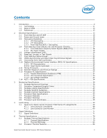
Listing by Land Number 60 5 Signal Definitions ...71 5.1 Signal Definitions 71 6 Thermal Specifications 79 6.1 Package Thermal Specifications 79 6.1.1 Thermal Specifications 79 6.1.2 Thermal Metrology 83 6.2 Processor Thermal Features 84 Quad-Core Intel® Xeon® Processor 5300 Series Datasheet - Intel E5310 | Data Sheet - Page 4
Tools Specifications 111 9.1 Debug Port System Requirements 111 9.2 Target System Implementation 111 9.2.1 System Implementation 111 9.3 Logic Analyzer Interface (LAI 111 9.3.1 Mechanical Considerations 112 9.3.2 Electrical Considerations 112 4 Quad-Core Intel® Xeon® Processor 5300 Series - Intel E5310 | Data Sheet - Page 5
Lines 31 2-5 Quad-Core Intel® Xeon® Processor X5300 Series VCC Static and Transient Tolerance Load Lines 32 2-6 VCC Overshoot Example Waveform 34 2-7 Electrical Test Circuit 36 2-8 Differential Clock Waveform 36 2-9 Differential Clock Crosspoint Specification 37 3-1 Processor Package Assembly - Intel E5310 | Data Sheet - Page 6
Land Number 60 5-1 Signal Definitions 71 6-1 Quad-Core Intel® Xeon® Processor E5300 Series Thermal Specifications 80 6-2 Quad-Core Intel® Xeon® Processor E5300 Series Thermal Profile Table 81 6-3 Quad-Core Intel® Xeon® Processor X5300 Series Thermal Specifications 82 6-4 Quad-Core Intel® Xeon - Intel E5310 | Data Sheet - Page 7
Revision History Document Number 315569 Revision -001 Initial Release Description § Date November 2006 Quad-Core Intel® Xeon® Processor 5300 Series Datasheet 7 - Intel E5310 | Data Sheet - Page 8
8 Quad-Core Intel® Xeon® Processor 5300 Series Datasheet - Intel E5310 | Data Sheet - Page 9
-media units include 128-bit wide registers and a separate register for data movement. SSE3 instructions provide highly efficient doubleprecision floating point, SIMD integer, and memory management operations. The Quad-Core Intel® Xeon® Processor 5300 Series supports Intel® 64 architecture as an - Intel E5310 | Data Sheet - Page 10
developer.intel.com/technology/virtualization/index.htm. The Quad-Core Intel® Xeon® Processor 5300 Series are intended for high performance server and workstation systems. The processors support a Dual Independent Bus (DIB) architecture with one processor on each bus, up to two processor sockets in - Intel E5310 | Data Sheet - Page 11
Series and Quad-Core Intel® Xeon® Processor X5300 Series. • Quad-Core Intel® Xeon® Processor E5300 Series - A mainstream performance version of the Quad-Core Intel® Xeon® Processor E5300 Series. For this document "Quad-Core Intel® Xeon® Processor E5300 Series" is used to call out specifications that - Intel E5310 | Data Sheet - Page 12
improved performance by allowing increased FSB speeds and bandwidth. • Flexible Motherboard Guidelines (FMB) - Are estimates of the maximum values the Quad-Core Intel® Xeon® Processor 5300 Series will have over certain time periods. The values are only estimates and actual specifications for - Intel E5310 | Data Sheet - Page 13
, Volume 3A Intel® 64 and IA-32 Architectures Software Developer's Manual, Volume 3B IA-32 Intel® Architecture Optimization Reference Manual Intel® Virtualization Technology Specification for the IA-32 Intel® Architecture Quad-Core Intel® Xeon® Processor 5300 Series Specification Update Voltage - Intel E5310 | Data Sheet - Page 14
Introduction 14 Quad-Core Intel® Xeon® Processor 5300 Series Datasheet - Intel E5310 | Data Sheet - Page 15
Electrical Specifications 2 Electrical Specifications 2.1 Front Side Bus and GTLREF Most Quad-Core Intel® Xeon® Processor 5300 Series FSB signals use Assisted Gunning Transceiver Logic (AGTL+) signaling technology. This technology provides improved noise margins and reduced ringing through low - Intel E5310 | Data Sheet - Page 16
LGA771 socket. Bulk decoupling must be provided on the baseboard to handle large current swings. The power delivery solution must insure the voltage and current specifications load. To insure optimal performance, various factors associated with Quad-Core Intel® Xeon® Processor 5300 Series Datasheet - Intel E5310 | Data Sheet - Page 17
19. These specifications must be met while also meeting signal integrity requirements as outlined in Table 2-19. The processor utilizes differential clocks. Table 2-1 contains processor core frequency to FSB multipliers and their corresponding core frequencies. Quad-Core Intel® Xeon® Processor 5300 - Intel E5310 | Data Sheet - Page 18
Listed frequencies are not necessarily committed production frequencies. 3. For valid processor core frequencies, refer to the Quad-Core Intel® Xeon® Processor 5300 Series Specification Update. 4. The lowest bus ratio supported is 1/6. 2.4.1 Front Side Bus Frequency Select Signals (BSEL[2:0]) Upon - Intel E5310 | Data Sheet - Page 19
. The specifications have been set such that one voltage regulator can operate with all supported frequencies. Individual processor VID values Quad-Core Intel® Xeon® Processor 5300 Series. Please refer to the appropriate platform design guide for details. The Quad-Core Intel® Xeon® Processor - Intel E5310 | Data Sheet - Page 20
0 1 0 0 0.9625 66 1 1 0 0 1 1 0.9750 64 1 1 0 0 1 0 0.9875 62 1 1 0 0 0 specific VID off code is received, the VRM/EVRD must turn off its output (the output should go to high impedance) within 500 ms and latch off until power is cycled. 20 Quad-Core Intel® Xeon® Processor - Intel E5310 | Data Sheet - Page 21
Specifications Table 2-4. Loadline Selection Truth Table for LL_ID[1:0] LL_ID1 0 0 1 1 LL_ID0 0 1 0 1 Description Reserved Dual-Core Intel® Xeon® Processor 5000 Series Dual-Core Intel® Xeon® Processor 5100 Series Reserved All Quad-Core Intel® Xeon® Processor For each processor socket, connect - Intel E5310 | Data Sheet - Page 22
Electrical Specifications The TESTHI signals may use individual pull-up resistors or be grouped together as Drain Output Synchronous to BCLK[1:0] Asynchronous ADSTB[1:0]#, DSTBP[3:0]#, DSTBN[3:0]# FERR#/PBE#, IERR#, PROCHOT#, THERMTRIP# 22 Quad-Core Intel® Xeon® Processor 5300 Series Datasheet - Intel E5310 | Data Sheet - Page 23
by multiple agents (Wired-OR). 3. Not all Quad-Core Intel® Xeon® Processor 5300 Series support the additional signals A[37:36]#. Processors that support these signals will be outlined in the Quad-Core Intel® Xeon® Processor 5300 Series Specification Update. Table 2-7 and Table 2-8 outline the - Intel E5310 | Data Sheet - Page 24
#, TCK, TDI, TMS, TRST# Note: 1. Not all Quad-Core Intel® Xeon® Processor 5300 Series support the additional signals A[37:36]#. Processors that support these signals will be outlined in the Quad-Core Intel® Xeon® Processor 5300 Series Specification Update. 2.8 CMOS Asynchronous and Open Drain - Intel E5310 | Data Sheet - Page 25
/max specifications. 2. The leakage specification applies to guide for input buffer design. Figure 2-1. Input Device Hysteresis VTT Maximum VP Minimum VP Maximum VN Minimum VN PECI Ground PECI High Range PECI Low Range Minimum Valid Input Hysteresis Signal Range Quad-Core Intel® Xeon® Processor - Intel E5310 | Data Sheet - Page 26
thermal specifications must be satisfied. 2. Overshoot and undershoot voltage guidelines for input, output, and I/O signals are outlined in Section 3. Excessive overshoot or undershoot on any signal will likely result in permanent damage to the processor. 26 Quad-Core Intel® Xeon® Processor 5300 - Intel E5310 | Data Sheet - Page 27
2-12. Voltage and Current Specifications (Sheet 1 of 2) Symbol VID VCC VCC_BOOT VVID_STEP VVID_SHIFT VTT VCCPLL Parameter Min Typ Max VID range for Quad-Core Intel® Xeon® Processor E5300 Series and Quad-Core Intel® Xeon® Processor X5300 Series VCC for processor core Launch - FMB Default VCC - Intel E5310 | Data Sheet - Page 28
Specifications (Sheet 2 of 2) Symbol ICC ICC_RESET ICC ICC_RESET ITT ICC_TDC ICC_TDC ICC_VTT_OUT ICC_GTLREF ICC_VCCPLL ITCC ITCC Parameter ICC for Quad-Core Intel® Xeon® Processor E5300 Series core with multiple VID Launch - FMB ICC_RESET for Quad-Core Intel® Xeon® Processor E5300 Series core - Intel E5310 | Data Sheet - Page 29
specification does not include the current coming from on-board termination (RTT), through the signal line. Refer to the appropriate platform design guide is specified while PWRGOOD and RESET# are asserted. Quad-Core Intel® Xeon® Processor E5300 Series Load Current versus Time Sustained Current (A) - Intel E5310 | Data Sheet - Page 30
Electrical Specifications Figure 2-3. Quad-Core Intel® Xeon® Processor X5300 Series Load Current versus Time Sustained Current (A) 13 0 12 5 12 0 115 110 10 5 10 0 0 .0 1 0 .1 1 10 10 0 10 0 0 Tim e Duration (s) Notes: 1. Processor or voltage regulator thermal protection circuitry - Intel E5310 | Data Sheet - Page 31
limits. Please see Section 2.13.2 for VCC overshoot specifications. 2. This table is intended to aid in reading discrete points on Figure 2-4 for Quad-Core Intel® Xeon® Processor E5300 Series, Figure 2-5 for Quad-Core Intel® Xeon® Processor X5300 Series. 3. The loadlines specify voltage limits at - Intel E5310 | Data Sheet - Page 32
from VTT with a 1% tolerance resistor divider. The VTT referred to in these specifications is the instantaneous VTT. 7. Specified when on-die RTT and RON are turned off. VIN between 0 and VTT. 8. This is the measurement at the pin. 32 Quad-Core Intel® Xeon® Processor 5300 Series Datasheet - Intel E5310 | Data Sheet - Page 33
and VSS_DIE_SENSE2 lands. Table 2-17. VCC Overshoot Specifications Symbol Parameter Min VOS_MAX TOS_MAX Magnitude of VCC overshoot above VID Time duration of VCC overshoot above VID Max 50 25 Units mV µs Figure 2-6 2-6 Notes Quad-Core Intel® Xeon® Processor 5300 Series Datasheet 33 - Intel E5310 | Data Sheet - Page 34
of processor die level overshoot should be taken with a 100 MHz bandwidth limited oscilloscope. 2.14 AGTL+ FSB Specifications Routing topologies are dependent on the processors supported and design guidelines for implementation details. 34 Quad-Core Intel® Xeon® Processor 5300 Series Datasheet - Intel E5310 | Data Sheet - Page 35
of the minimum voltage. 7. Ringback Margin is defined as the absolute voltage difference between the maximum Rising Edge Ringback and the maximum Falling Edge Ringback. Quad-Core Intel® Xeon® Processor 5300 Series Datasheet 35 - Intel E5310 | Data Sheet - Page 36
hysteresis. 9. The crossing point must meet the absolute and relative crossing point specifications simultaneously. 10. VHavg can be measured directly using "Vtop" on Agilent and Rising Edge Ringback Falling Edge Ringback, VL Undershoot 36 Quad-Core Intel® Xeon® Processor 5300 Series Datasheet - Intel E5310 | Data Sheet - Page 37
2-9. Differential Clock Crosspoint Specification Crossing Point (mV) 650 600 550 500 550 + 0.5 (VHavg - 700) 450 550 mV Note: Please refer to Table 2-15 for TAP Signal Group DC specifications for TAP Signal Group AC specifications. § Quad-Core Intel® Xeon® Processor 5300 Series Datasheet 37 - Intel E5310 | Data Sheet - Page 38
Electrical Specifications 38 Quad-Core Intel® Xeon® Processor 5300 Series Datasheet - Intel E5310 | Data Sheet - Page 39
Mechanical Specifications 3 Mechanical Specifications The Quad-Core Intel® Xeon® Processor 5300 Series are packaged in a Flip Chip Land Grid Array (FC-LGA6) package that interfaces to the baseboard via a LGA771 socket. The package consists of two processor dies mounted on a pinless substrate with - Intel E5310 | Data Sheet - Page 40
(Sheet 1 of 3) Mechanical Specifications Note: Guidelines on potential IHS flatness variation with socket load plate actuation and installation of the cooling solution is available in the processor Thermal/Mechanical Design Guidelines. 40 Quad-Core Intel® Xeon® Processor 5300 Series Datasheet - Intel E5310 | Data Sheet - Page 41
Mechanical Specifications Figure 3-3. Processor Package Drawing (Sheet 2 of 3) Quad-Core Intel® Xeon® Processor 5300 Series Datasheet 41 - Intel E5310 | Data Sheet - Page 42
Figure 3-4. Processor Package Drawing (Sheet 3 of 3) Mechanical Specifications 42 Quad-Core Intel® Xeon® Processor 5300 Series Datasheet - Intel E5310 | Data Sheet - Page 43
NA 750 me 1,3,7,8 Notes: 1. These specifications apply to uniform compressive loading in a direction LGA771 Socket. 9. Refer to the Quad-Core Intel® Xeon® Processor 5300 Series Thermal/Mechanical Design Guidelines for information on heatsink clip load metrology. Quad-Core Intel® Xeon® Processor - Intel E5310 | Data Sheet - Page 44
Insertion Specifications The Quad-Core Intel® Xeon® Processor 5300 Series can be inserted and removed 15 times from an LGA771 socket, which meets the criteria outlined in the LGA771 Socket Design Guidelines. 3.6 Processor Mass Specifications The typical mass of the Quad-Core Intel® Xeon® Processor - Intel E5310 | Data Sheet - Page 45
Mechanical Specifications 3.8 Processor Markings Figure 3-5 shows the topside markings on the processor. This diagram aids in the identification of the Quad-Core Intel® Xeon® Processor 5300 Series. Figure 3-5. Processor Top-side Markings (Example) 3.9 GROUP1LINE1 GROUP1LINE2 GROUP1LINE3 - Intel E5310 | Data Sheet - Page 46
Specifications Figure 3-6. Processor Land Coordinates, Top View VCC / VSS 30 29 28 27 26 25 24 23 22 21 20 19 18 17 16 15 14 13 12 11 10 9 8 7 6 5 4 3 2 1 AN AM AL AK AJ AH AG AF AE AD AC AB AA Y W Socket F E D C B A 46 Quad-Core Intel® Xeon® Processor 5300 Series Datasheet - Intel E5310 | Data Sheet - Page 47
Mechanical Specifications Figure 3-7. Processor Land Coordinates, Socket 771 W V Quadrants U T Bottom View R P N M L K J H G F E D C B A 1 2 3 4 5 6 7 8 9 10 11 12 13 14 15 16 17 18 19 20 21 22 23 24 25 26 27 28 29 30 Data VTT / Clocks § Quad-Core Intel® Xeon® Processor - Intel E5310 | Data Sheet - Page 48
Mechanical Specifications 48 Quad-Core Intel® Xeon® Processor 5300 Series Datasheet - Intel E5310 | Data Sheet - Page 49
4.1 Quad-Core Intel® Xeon® Processor 5300 Series Pin Assignments This section provides sorted land list in Table 4-1 and Table 4-2. Table 4-1 is a listing of all processor lands ordered alphabetically by land name. Table 4-2 is a listing of all processor lands ordered by land number. 4.1.1 Land - Intel E5310 | Data Sheet - Page 50
Input/ Output Input/ Output Input/ Output Input/ Output Input/ Output Input/ Output Input/ Output Input/ Output Input/ Output Input/ Output Input/ Output Input/ Output 50 Quad-Core Intel® Xeon® Processor 5300 Series Datasheet - Intel E5310 | Data Sheet - Page 51
/ Output Output Input/ Output Input Input/ Output Input/ Output Input/ Output Input/ Output Input/ Output Input/ Output Input/ Output Input/ Output Input/ Output Input/ Output Quad-Core Intel® Xeon® Processor 5300 Series Datasheet 51 - Intel E5310 | Data Sheet - Page 52
E6 E7 F23 F29 F6 G6 J2 J3 N5 T2 Y1 Y3 G23 B3 Signal Buffer Type Direction Common Clk Common Clk Input Input 52 Quad-Core Intel® Xeon® Processor 5300 Series Datasheet - Intel E5310 | Data Sheet - Page 53
Power/Other Power/Other Power/Other Power/Other Power/Other Power/Other Power/Other Power/Other Power/Other Power/Other Power/Other Power/Other Direction Quad-Core Intel® Xeon® Processor 5300 Series Datasheet 53 - Intel E5310 | Data Sheet - Page 54
Power/Other AN19 Power/Other AN21 Power/Other AN22 Power/Other AN25 Power/Other AN26 Power/Other AN8 Power/Other AN9 Power/Other Direction 54 Quad-Core Intel® Xeon® Processor 5300 Series Datasheet - Intel E5310 | Data Sheet - Page 55
Power/Other Power/Other Power/Other Power/Other Power/Other Power/Other Power/Other Power/Other Power/Other Power/Other Power/Other Power/Other Direction Quad-Core Intel® Xeon® Processor 5300 Series Datasheet 55 - Intel E5310 | Data Sheet - Page 56
/Other Power/Other Power/Other Power/Other Power/Other Power/Other Power/Other Power/Other Power/Other Power/Other Power/Other Power/Other Direction 56 Quad-Core Intel® Xeon® Processor 5300 Series Datasheet - Intel E5310 | Data Sheet - Page 57
AN17 Power/Other AN2 Power/Other AN20 Power/Other AN23 Power/Other AN24 Power/Other B1 Power/Other B11 Power/Other B14 Power/Other Direction Quad-Core Intel® Xeon® Processor 5300 Series Datasheet 57 - Intel E5310 | Data Sheet - Page 58
/Other Power/Other Power/Other Power/Other Power/Other Power/Other Power/Other Power/Other Power/Other Power/Other Power/Other Power/Other Direction 58 Quad-Core Intel® Xeon® Processor 5300 Series Datasheet - Intel E5310 | Data Sheet - Page 59
Power/Other Power/Other Power/Other Power/Other Power/Other Power/Other Power/Other Power/Other Power/Other Power/Other Output Output Output Output Output Quad-Core Intel® Xeon® Processor 5300 Series Datasheet 59 - Intel E5310 | Data Sheet - Page 60
Input/Output Input/Output Input/Output Output Output Input/Output Input/Output Table 4-2. Land Listing by Land Number (Sheet 2 of 20) Pin No. Pin Name AA7 AA8 AB1 AB2 AB23 VSS VCC VSS IERR /Other Power/Other Input/Output Input Output 60 Quad-Core Intel® Xeon® Processor 5300 Series Datasheet - Intel E5310 | Data Sheet - Page 61
Input/Output Input Power/Other Power/Other Power/Other Power/Other Output Table 4-2. Land Listing by Land Number (Sheet 4 of 20) Pin No. Pin Name AE9 VCC AF1 TDO AF10 VSS AF11 VCC Other Output Output Input/Output Input/Output Input Quad-Core Intel® Xeon® Processor 5300 Series Datasheet 61 - Intel E5310 | Data Sheet - Page 62
Other Power/Other Power/Other Power/Other Power/Other Power/Other Power/Other Table 4-2. Land Listing by Land Number (Sheet 6 of 20) Pin No. Pin Name AH27 VCC AH28 VCC AH29 VCC AH3 VSS AH30 Sync Input/Output Input/Output Power/Other 62 Quad-Core Intel® Xeon® Processor 5300 Series Datasheet - Intel E5310 | Data Sheet - Page 63
Power/Other Power/Other Power/Other Power/Other Power/Other Power/Other Table 4-2. Land Listing by Land Number (Sheet 8 of 20) Pin No. Pin Name AL18 VCC AL19 VCC AL2 PROCHOT# AL20 VSS Power/Other Power/Other Power/Other Power/Other Quad-Core Intel® Xeon® Processor 5300 Series Datasheet 63 - Intel E5310 | Data Sheet - Page 64
/Other Power/Other Power/Other Source Sync Power/Other Output Input/Output Table 4-2. Land Listing by Land Number (Sheet 10 of 20) Pin No. Pin Name B12 D13# B13 RESERVED B14 VSS B15 D53# /Output Input/Output Input/Output Input/Output 64 Quad-Core Intel® Xeon® Processor 5300 Series Datasheet - Intel E5310 | Data Sheet - Page 65
Other Input/Output Input/Output Input/Output Input/Output Input/Output Input Table 4-2. Land Listing by Land Number (Sheet 12 of 20) Pin No. Pin Name D30 D4 D5 D6 D7 D8 D9 E1 E10 /Other Power/Other Source Sync Input/Output Input/Output Quad-Core Intel® Xeon® Processor 5300 Series Datasheet 65 - Intel E5310 | Data Sheet - Page 66
/Output Input/Output Input/Output Input/Output Input/Output Input Input/Output Table 4-2. Land Listing by Land Number (Sheet 14 of 20) Pin No. G21 G22 G23 G24 G25 G26 G27 G28 G29 G3 G30 Input/Output Input Input/Output Input/Output Input 66 Quad-Core Intel® Xeon® Processor 5300 Series Datasheet - Intel E5310 | Data Sheet - Page 67
Other ASync GTL+ Power/Other Power/Other Input/Output Input/Output Input Table 4-2. Land Listing by Land Number (Sheet 16 of 20) Pin No. Pin Name K24 K25 K26 K27 K28 K29 K3 K30 /Output Input Input Input/Output Input/Output Output Input Quad-Core Intel® Xeon® Processor 5300 Series Datasheet 67 - Intel E5310 | Data Sheet - Page 68
Power/Other Power/Other Input Input Input Input/Output Input/Output Input Table 4-2. Land Listing by Land Number (Sheet 18 of 20) Pin No. Pin Name R24 R25 R26 R27 R28 R29 R3 R30 R4 /Output Input/Output Input Input/Output Input/Output 68 Quad-Core Intel® Xeon® Processor 5300 Series Datasheet - Intel E5310 | Data Sheet - Page 69
Input/Output Input/Output Output Output Input/Output Input/Output Output Input Table 4-2. Land Listing by Land Number (Sheet 20 of 20) Pin No. Pin Name W27 W28 W29 W3 W30 W4 W5 W6 Power/Other Power/Other Input/Output Input/Output § Quad-Core Intel® Xeon® Processor 5300 Series Datasheet 69 - Intel E5310 | Data Sheet - Page 70
Land Listing 70 Quad-Core Intel® Xeon® Processor 5300 Series Datasheet - Intel E5310 | Data Sheet - Page 71
of covered signals are low and low if an odd number of covered signals are low. This allows parity to be high when all the covered signals are high. AP[1:0]# must be connected to the appropriate pins of all Quad-Core Intel® Xeon® Processor 5300 Series FSB agents. The following table defines the - Intel E5310 | Data Sheet - Page 72
. COMP[3:0] must be terminated to VSS on the baseboard using precision resistors. These inputs configure the AGTL+ drivers of the processor. Refer to the appropriate platform design guidelines for implementation details. Notes 3 3 2 2 3 3 72 Quad-Core Intel® Xeon® Processor 5300 Series Datasheet - Intel E5310 | Data Sheet - Page 73
64-bit data path between the processor FSB agents, and must connect the appropriate pins on all such agents. The data driver asserts DRDY# to indicate a valid data transfer. D[63:0]# are quad connect on the Quad-Core Intel® Xeon® Processor 5300 Series package. DBR# is not a processor signal. I/O - Intel E5310 | Data Sheet - Page 74
Intel® 64 and IA-32 Intel® Architecture Software Developer's Manual and the AP-485 Intel® Processor Identification and the CPUID Instruction application note. FORCEPR# I The FORCEPR# (force power reduction) input can be used by the platform to cause the Quad-Core Intel® Xeon® Processor 5300 - Intel E5310 | Data Sheet - Page 75
Guide. These signals are provided to indicate the Market Segment for the processor and may be used for future processor compatibility or for keying. These signals are not connected to the processor die. A logic 0 is pulled to ground and a logic 1 is a noconnect on the Quad-Core Intel® Xeon - Intel E5310 | Data Sheet - Page 76
into the processor. TDI provides the serial input needed for JTAG specification support. TDO (Test Data Out) transfers serial test data out of the processor. TDO provides the serial output needed for JTAG specification support. Notes 2 3 3 3 3 2 2 76 Quad-Core Intel® Xeon® Processor 5300 Series - Intel E5310 | Data Sheet - Page 77
land of the same socket for proper processor operation. TESTIN2 must be needed to support processor voltage specification variations. processor voltage) remains within specification. Please see the applicable platform design guide for implementation details. Notes 1 Quad-Core Intel® Xeon® Processor - Intel E5310 | Data Sheet - Page 78
Maximum number of priority agents is one. 4. Not all Quad-Core Intel® Xeon® Processor 5300 Series support signals A[37:36]#. Processors that support these signals will be outlined in the Quad-Core Intel® Xeon® Processor 5300 Series Specification Update. § 78 Quad-Core Intel® Xeon® Processor 5300 - Intel E5310 | Data Sheet - Page 79
fan speed only need to guarantee the case temperature meets the thermal profile specifications. The Quad-Core Intel® Xeon® Processor E5300 Series (see Figure 6-1; Table 6-2) supports a single Thermal Profile. For these processors, it is expected that the Thermal Control Circuit (TCC) would only be - Intel E5310 | Data Sheet - Page 80
of TCC activation and performance loss is increased. Additionally, utilization of a thermal solution that does not meet Thermal Profile B will violate the thermal specifications and may result in permanent damage to the processor. Refer to the Quad-Core Intel® Xeon® Processor 5300 Series Thermal - Intel E5310 | Data Sheet - Page 81
Thermal Specifications 6. FMB, or Flexible Motherboard, guidelines provide a design target for meeting all planned processor frequency requirements. Figure 6-1.Quad-Core Intel® Xeon® Processor E5300 Series Thermal Profile Tcase [C] 70 65 60 Thermal Profile Y = 0.293*x + 42.6 55 50 45 40 0 - Intel E5310 | Data Sheet - Page 82
activation and measurable performance loss. Furthermore, utilization of thermal solutions that do not meet Thermal Profile B do not meet the processor's thermal specifications and may result in permanent damage to the processor. 5. Refer to the Quad-Core Intel® Xeon® Processor 5300 Series Thermal - Intel E5310 | Data Sheet - Page 83
Specifications Table 6-4. Quad-Core Intel® Xeon® Processor Core Intel® Xeon® Processor X5300 Series Thermal Profile B Table Power (W) P_PROFILE_MIN_B=30.8 35 40 45 50 55 60 65 70 75 80 85 90 95 100 105 110 115 120 TCASE_MAX (°C) 50.0 50.9 52.1 53.2 54.3 55.4 56.5 57.7 58.8 59.9 61.0 62.1 63.3 64 - Intel E5310 | Data Sheet - Page 84
Features Thermal Monitor Features Quad-Core Intel® Xeon® Processor 5300 Series provide two thermal monitor features, Thermal Monitor (TM1) and Enhanced Thermal Monitor (TM2). The TM1 and TM2 must both be enabled in BIOS for the processor to be operating within specifications. When both are enabled - Intel E5310 | Data Sheet - Page 85
Quad-Core Intel® Xeon® Processor X5300 Series Thermal Profile B may cause a noticeable performance loss due to increased TCC activation. Thermal Solutions that exceed Thermal Profile B will exceed the maximum temperature specification The Quad-Core Intel® Xeon® Processor 5300 Series adds support for - Intel E5310 | Data Sheet - Page 86
level power consumption. Systems utilizing the Quad-Core Intel® Xeon® Processor 5300 Series must not rely on software usage of this mechanism to limit the processor temperature. If bit 4 of the IA32_CLOCK_MODULATION MSR is set to a '1', the processor will immediately reduce its power consumption - Intel E5310 | Data Sheet - Page 87
Thermal Monitor to become active. Please refer to the Quad-Core Intel® Xeon® Processor 5300 Series Specification Update to determine which processors support TM2 and Intel® 64 and IA-32 Architecture Software Developer's Manual for details on enabling these capabilities. Assertion of the FORCEPR - Intel E5310 | Data Sheet - Page 88
to 2 Mbps). The PECI interface on Quad-Core Intel® Xeon® Processor 5300 Series is disabled by default and must be enabled through BIOS. More information on this can be found in the Intel® 64 and IA-32 Architecture Software Developer's Manual. Figure 6-5. PECI Topology 6.3.1.1 PECI Host C ontroller - Intel E5310 | Data Sheet - Page 89
control algorithm. PECI Specifications PECI Device Address The PECI device address for socket 0 is 0x30 and socket 1 is 0x31. Please note that each address also supports two domains (Domain within, and thus given operating conditions Quad-Core Intel® Xeon® Processor 5300 Series Datasheet 89 - Intel E5310 | Data Sheet - Page 90
that fall under the specification, the PECI client 6.3.2.3 PECI GetTemp0() and GetTemp1() Error Code Support The error codes supported for the processor GetTemp0() and GetTemp1() command are listed in operational range (underflow). § 90 Quad-Core Intel® Xeon® Processor 5300 Series Datasheet - Intel E5310 | Data Sheet - Page 91
the EXT_CONFIG Model Specific Register (MSR). This MSR will allow for the disabling of a single core per die within the Quad-Core Intel® Xeon® Processor 5300 Series package. Additional details can be found in the Intel® 64 and IA-32 Architecture Software Developer's Manual. 7.2 Clock Control and - Intel E5310 | Data Sheet - Page 92
(C1E) is enabled via the BIOS. Refer to the Intel® 64 and IA-32 Architecture Software Developer's Manual. The Extended HALT state must be enabled for the processor to remain within its specifications. The Extended HALT state requires support for dynamic VID transitions in the platform. HALT State - Intel E5310 | Data Sheet - Page 93
Maximum Power Symbol PEXTENDED_HALT Quad-Core Intel® Xeon® Processor E5300 Series PEXTENDED_HALT QuadCore Intel® Xeon® Processor X5300 Series Parameter Extended HALT State Power Extended HALT State Power Min Typ Max 30/34 Unit W Notes 1,2,3 50 W 1,2 Notes: 1. The specification is at TCASE - Intel E5310 | Data Sheet - Page 94
(whether by the processor or another agent on the front side bus) or the interrupt has been latched. After the snoop is serviced or the interrupt is latched, the processor will return to the Stop-Grant state or HALT state, as appropriate. 94 Quad-Core Intel® Xeon® Processor 5300 Series Datasheet - Intel E5310 | Data Sheet - Page 95
. More details on which processor frequencies will support this feature will be provided in future releases of the Quad-Core Intel® Xeon® Processor 5300 Series Specification Update when available. Enhanced Intel SpeedStep Technology creates processor performance states (P-states) or voltage - Intel E5310 | Data Sheet - Page 96
Features 96 Quad-Core Intel® Xeon® Processor 5300 Series Datasheet - Intel E5310 | Data Sheet - Page 97
Specifications 8.1 Introduction Intel boxed processors are intended for system integrators who build systems from components available through distribution channels. The Quad-Core Intel® Xeon® Processor 5300 Series will be offered as an Intel boxed processor. Intel will offer the Quad-Core Intel - Intel E5310 | Data Sheet - Page 98
Boxed Processor Specifications Figure 8-2. Boxed Quad-Core Intel® Xeon® Processor 5300 Series 2U Passive Heat Sink Figure 8-3. 2U Passive Quad-Core Intel® Xeon® Processor 5300 Series Processor Thermal Solution (Exploded View) Heat sink screws Heat sink screw springs Heat sink Heat sink standoffs - Intel E5310 | Data Sheet - Page 99
for the boxed processor and assembled heat sink are shown in Figure 8-4 through Figure 8-8. Figure 8-9 through Figure 8-10 are the mechanical drawings for the 4-pin board fan header and 4-pin connector used for the active CEK fan heat sink solution. Quad-Core Intel® Xeon® Processor 5300 Series - Intel E5310 | Data Sheet - Page 100
Figure 8-4. Top Side Board Keepout Zones (Part 1) Boxed Processor Specifications 100 Quad-Core Intel® Xeon® Processor 5300 Series Datasheet - Intel E5310 | Data Sheet - Page 101
Boxed Processor Specifications Figure 8-5. Top Side Board Keepout Zones (Part 2) Quad-Core Intel® Xeon® Processor 5300 Series Datasheet 101 - Intel E5310 | Data Sheet - Page 102
Figure 8-6. Bottom Side Board Keepout Zones Boxed Processor Specifications 102 Quad-Core Intel® Xeon® Processor 5300 Series Datasheet - Intel E5310 | Data Sheet - Page 103
Boxed Processor Specifications Figure 8-7. Board Mounting-Hole Keepout Zones Quad-Core Intel® Xeon® Processor 5300 Series Datasheet 103 - Intel E5310 | Data Sheet - Page 104
Figure 8-8. Volumetric Height Keep-Ins Boxed Processor Specifications 104 Quad-Core Intel® Xeon® Processor 5300 Series Datasheet - Intel E5310 | Data Sheet - Page 105
Boxed Processor Specifications Figure 8-9. 4-Pin Fan Cable Connector (For Active CEK Heat Sink) Quad-Core Intel® Xeon® Processor 5300 Series Datasheet 105 - Intel E5310 | Data Sheet - Page 106
Boxed Processor Specifications Figure 8-10. 4-Pin Base Board Fan Header (For Active CEK Heat Sink) 106 Quad-Core Intel® Xeon® Processor 5300 Series Datasheet - Intel E5310 | Data Sheet - Page 107
support the boxed processor. Refer to the Server System Infrastructure Specification (SSI-EEB 3.6, TEB 2.1 or CEB 1.1). These specification solution is connected to an older 3-pin baseboard CPU fan header it will default back to a thermistor Quad-Core Intel® Xeon® Processor 5300 Series Datasheet 107 - Intel E5310 | Data Sheet - Page 108
the processor's temperature specifications is also the function of the thermal design of the entire system, and ultimately the responsibility of the system integrator. The processor temperature specifications are found in Section 6 of this document. 108 Quad-Core Intel® Xeon® Processor 5300 - Intel E5310 | Data Sheet - Page 109
required to cool the processor. The board must not bend beyond specification in order to avoid damage. The boxed processor contains the components necessary to solve both issues. The boxed processor will include the following items: • Quad-Core Intel® Xeon® Processor 5300 Series • Unattached heat - Intel E5310 | Data Sheet - Page 110
Processor Specifications The other items listed in Figure 8-3 that are required to compete this solution will be shipped with either the chassis or boards. They are as follows: • CEK Spring (supplied by baseboard vendors) • Heat sink standoffs (supplied by chassis vendors) § 110 Quad-Core Intel - Intel E5310 | Data Sheet - Page 111
Please refer to the Debug Port Design Guide for UP/DP Systems and the appropriate platform design guidelines for information regarding debug tool specifications. Section 1.3 provides collateral details. Debug Port System Requirements The Quad-Core Intel® Xeon® Processor 5300 Series debug port is the - Intel E5310 | Data Sheet - Page 112
cooling solution. Electrical Considerations The LAI will also affect the electrical performance of the FSB, therefore it is critical to obtain electrical load electrical specifications and load models for the LAI solution they provide. § 112 Quad-Core Intel® Xeon® Processor 5300 Series Datasheet
-
 1
1 -
 2
2 -
 3
3 -
 4
4 -
 5
5 -
 6
6 -
 7
7 -
8
-
9
-
10
-
11
-
12
-
13
-
14
-
15
-
16
-
17
-
18
-
19
-
20
-
21
-
22
-
23
-
24
-
25
-
26
-
27
-
28
-
29
-
30
-
31
-
32
-
33
-
34
-
35
-
36
-
37
-
38
-
39
-
40
-
41
-
42
-
43
-
44
-
45
-
46
-
47
-
48
-
49
-
50
-
51
-
52
-
53
-
54
-
55
-
56
-
57
-
58
-
59
-
60
-
61
-
62
-
63
-
64
-
65
-
66
-
67
-
68
-
69
-
70
-
71
-
72
-
73
-
74
-
75
-
76
-
77
-
78
-
79
-
80
-
81
-
82
-
83
-
84
-
85
-
86
-
87
-
88
-
89
-
90
-
91
-
92
-
93
-
94
-
95
-
96
-
97
-
98
-
99
-
100
-
101
-
102
-
103
-
104
-
105
-
106
-
107
-
108
-
109
-
110
-
111
-
112
 |
 |

Order Number: 315569, Revision: 001
Quad-Core Intel® Xeon® Processor
5300 Series
Datasheet
November 2006