Intel E6700 Mechanical Design Guidelines
Intel E6700 - Core 2 Duo Dual-Core Processor Manual
 |
UPC - 735858184618
View all Intel E6700 manuals
Add to My Manuals
Save this manual to your list of manuals |
Intel E6700 manual content summary:
- Intel E6700 | Mechanical Design Guidelines - Page 1
Intel® Core™2 Duo Processor E8000∆ and E7000∆ Series, Intel® Pentium® Dual-Core Processor E6000∆ and E5000∆ Series, and Intel® Celeron® Processor E3000∆ Series Thermal and Mechanical Design Guidelines November 2010 Document Number: 318734-017 - Intel E6700 | Mechanical Design Guidelines - Page 2
intel.com . The Intel® Core™2 Duo processor E8000, E7000 series and Intel® Pentium® Dual-Core processor E6000, E5000 series and Intel® Celeron® processor E3000 series components may contain design defects or errors known as errata, which may cause the product to deviate from published specifications - Intel E6700 | Mechanical Design Guidelines - Page 3
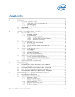
Attach 15 2.1.2.1 General Guidelines 15 2.1.2.2 Heatsink Clip Load Requirement 15 2.1.2.3 Additional Guidelines 16 2.2 Thermal Requirements 16 2.2.1 Processor Case Temperature 16 2.2.2 Thermal Profile 17 2.2.3 Thermal Solution Design Requirements 17 2.2.4 TCONTROL 18 2.3 Heatsink Design - Intel E6700 | Mechanical Design Guidelines - Page 4
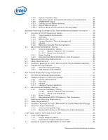
43 5.2.1.2 Shock Test Procedure 44 5.2.2 Power Cycling 45 5.2.3 Recommended BIOS/CPU/Memory Test Procedures 46 5.3 Material and Recycling Requirements 46 5.4 Safety Requirements 47 5.5 Geometric Envelope for Intel® Reference BTX Thermal Module Assembly ......47 5.6 Preload and TMA Stiffness 48 - Intel E6700 | Mechanical Design Guidelines - Page 5
Designs Non-Compliant with Intel® Reference Design 69 A.3 Heatsink Preload Requirement Limitations 69 A.3.1 Motherboard Deflection Metric Definition 70 Temperature Reference Metrology 83 D.1 Objective and Scope 83 D.2 Supporting Test Equipment 83 D.3 Thermal Calibration and Controls 85 D.4 - Intel E6700 | Mechanical Design Guidelines - Page 6
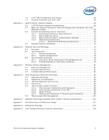
Figure 5-4. Intel® Type II TMA 65W Reference Design 47 Figure 5-5. Upward Board Deflection During Shock 48 Figure 5-6. Minimum Required Processor Preload to 6-8. Critical Core Dimension 62 Figure 7-1. Intel® QST Overview 64 Figure 7-2. PID Controller Fundamentals 65 Figure 7-3. Intel® QST - Intel E6700 | Mechanical Design Guidelines - Page 7
39. Thermal sensor Location Illustration 105 Figure 7-40. ATX/µATX Motherboard Keep-out Footprint Definition and Height Restrictions for Enabling Components - Sheet Temperature of Intel® Reference Thermal Solutions..........22 Table 2-2. Heatsink Inlet Temperature of Intel® Boxed Processor Thermal - Intel E6700 | Mechanical Design Guidelines - Page 8
Pentium dual-core processor E5200 • Added Intel® Core™2 Duo processor E7400 • Added Intel® Pentium dual-core processor E5300 • Added Intel® Pentium dual-core processor E5400 • Added Intel® Core™2 Duo processor E7500 • Added Intel® Pentium dual-core processor E6300 • Added Intel® Core™2 Duo processor - Intel E6700 | Mechanical Design Guidelines - Page 9
processor systems using the Intel® Core™2 Duo processor E8000, E7000 series, Intel® Pentium® dual-core processor E6000, E5000 series, and Intel® Celeron® processor E3000 series. The concepts given in this document are applicable to any system form factor. Specific examples used will be the Intel - Intel E6700 | Mechanical Design Guidelines - Page 10
-001) supported by this document. If needed for clarify, the specific reference design will be listed. In this document, when a reference is made to "the datasheet", the reader should refer to the Intel® Core™2 Duo Processor E8000 and E7000 Series Datasheet, Intel® Pentium® Dual-Core Processor E6000 - Intel E6700 | Mechanical Design Guidelines - Page 11
this document. Document Intel® Core™2 Duo Processor E8000 and E7000 Series Datasheet Intel® Pentium® Dual-Core Processor E6000 and E5000 Series Datasheet Intel® Celeron® Processor E3000 Series Datasheet LGA775 Socket Mechanical Design Guide uATX SFF Design Guidance Fan Specification for 4-wire PWM - Intel E6700 | Mechanical Design Guidelines - Page 12
as a dimension away from the outside dimension of the fins to the nearest surface. A feature on the processor that attempts to keep the processor die temperature within factory specifications. Thermal Control Circuit: Thermal Monitor uses the TCC to reduce die temperature by lowering the effective - Intel E6700 | Mechanical Design Guidelines - Page 13
the motherboard using a LGA775 socket. Refer to the datasheet for detailed mechanical specifications. The processor connects to the motherboard through to the motherboard. The socket is named LGA775 socket. A description of the socket can be found in the LGA775 Socket Mechanical Design Guide. The - Intel E6700 | Mechanical Design Guidelines - Page 14
interfaces with the LGA775 socket load plate, as described in LGA775 Socket Mechanical Design Guide. The load from the load plate is distributed across two sides of the IHS, it should not exceed the corresponding specification given in the processor datasheet. • When a compressive static load - Intel E6700 | Mechanical Design Guidelines - Page 15
shock and vibration that the system must support. The overall structural design of the motherboard and the system have to be considered when Design Guide for further information). 2.1.2.2 Heatsink Clip Load Requirement The attach mechanism for the heatsink developed to support the processor should - Intel E6700 | Mechanical Design Guidelines - Page 16
specifications described in the processor datasheet. One of the key design parameters is the height of the top surface of the processor IHS above the motherboard the socket seating plane above the motherboard after reflow, given in the LGA775 Socket Mechanical Design Guide with its tolerances. The - Intel E6700 | Mechanical Design Guidelines - Page 17
of 35 °C + 0.5 °C = 35.5 °C. The slope of the thermal profile was established assuming a generational improvement in thermal solution performance of the Intel reference design. For an example of Intel Core™2 Duo processor E8000 series with 6 MB in ATX platform, its improvement is about 15% over the - Intel E6700 | Mechanical Design Guidelines - Page 18
Intel Core™2 Duo processor E8000 series with 6 MB cache, Intel Core™2 Duo processor E7000 series with 3 MB cache, and Intel Pentium dual-core processor E6000 and E5000 series with 2 MB cache, and Intel Celeron processor TCONTROL parameter defines a very specific processor operating region where fan - Intel E6700 | Mechanical Design Guidelines - Page 19
can be used to program a fan speed control component. See the appropriate processor datasheet for further details on reading the register and calculating TCONTROL. See Chapter 7, Intel® Quiet System Technology (Intel® QST), for details on implementing a design using TCONTROL and the Thermal Profile - Intel E6700 | Mechanical Design Guidelines - Page 20
on the motherboard and other considerations for component height and placement in the area potentially impacted by the processor heatsink. The design guide. • The motherboard primary side height constraints defined in the ATX Specification V2.1 and the microATX Motherboard Interface Specification V1 - Intel E6700 | Mechanical Design Guidelines - Page 21
reference design structural ingredients is 900 grams. The BTX structural reference component strategy and design is reviewed in depth in the latest version of the Balanced Technology Extended (BTX) System Design Guide. Note: The 550g mass limit for ATX solutions is based on the capabilities of the - Intel E6700 | Mechanical Design Guidelines - Page 22
. Table 2-2. Heatsink Inlet Temperature of Intel® Boxed Processor Thermal Solutions Topic Boxed Processor for Intel® Core™2 Duo Processor E8000, E7000 Series, Intel® Pentium® Dual-Core Processor E6000, E5000 Series, and Intel® Celeron® Processor E3000 Series Heatsink Inlet Temperature 40 - Intel E6700 | Mechanical Design Guidelines - Page 23
feature and associated logic have been integrated into the silicon of the processor. By taking advantage of the Thermal Monitor feature, system designers may placed by the system System Integration Considerations Manufacturing with Intel® Components using 775-Land LGA Package and LGA775 Socket - Intel E6700 | Mechanical Design Guidelines - Page 24
Processor Thermal/Mechanical Information 24 Thermal and Mechanical Design Guidelines - Intel E6700 | Mechanical Design Guidelines - Page 25
thermal characterization parameter value (ΨCA) is used as a measure of the thermal performance of the overall thermal solution that is attached to the processor package. It is defined by the following equation, and measured in units of °C/W: ΨCA = (TC - TA) / PD (Equation 1) Where: ΨCA = Case-to - Intel E6700 | Mechanical Design Guidelines - Page 26
provides an illustration of how one might determine the appropriate performance targets. The example power and temperature numbers used here are not related to any specific Intel processor thermal specifications, and are for illustrative purposes only. 26 Thermal and Mechanical Design Guidelines - Intel E6700 | Mechanical Design Guidelines - Page 27
introduce additional factors that can impact test results. In particular, the power level from actual processors varies significantly, even when running the maximum power application provided by Intel, due to variances in the manufacturing process. The TTV provides consistent power and power density - Intel E6700 | Mechanical Design Guidelines - Page 28
setting against air temperature. When measuring TA in a chassis with a live motherboard, add-in cards, and other system components, it is likely that approximately 13 mm to 25 mm [0.5 to 1.0 in] away from processor and heatsink as shown in Figure 3-3. The thermocouples should be placed approximately - Intel E6700 | Mechanical Design Guidelines - Page 29
Thermal Metrology Figure 3-2. Locations for Measuring Local Ambient Temperature, Active ATX Heatsink Note: Drawing Not to Scale Figure 3-3. Locations for Measuring Local Ambient Temperature, Passive Heatsink Note: Drawing Not to Scale Thermal and Mechanical Design Guidelines 29 - Intel E6700 | Mechanical Design Guidelines - Page 30
and the heatsink base. Appendix D defines a reference procedure for attaching a thermocouple to the IHS of a 775-Land LGA processor package for TC measurement. This procedure takes into account the specific features of the 775-Land LGA package and of the LGA775 socket for which it is intended. § 30 - Intel E6700 | Mechanical Design Guidelines - Page 31
there are numerous ways to reduce the power consumption of a processor, and Intel is aggressively pursuing low power design techniques. For example, cost, by allowing thermal designs to target TDP. The processor also supports an additional power reduction capability known as Thermal Monitor 2 - Intel E6700 | Mechanical Design Guidelines - Page 32
As an output, PROCHOT# will go active when the processor temperature of either core reaches the TCC activation temperature. As an input, assertion the processor clocks off and then back on with a predetermined duty cycle. The duty cycle is processor specific, and is fixed for a particular processor. The - Intel E6700 | Mechanical Design Guidelines - Page 33
microseconds). During the frequency transition, the processor is unable to service any bus requests, all bus traffic processor will transition to the new core operating voltage by issuing a new VID code to the voltage regulator. The voltage regulator must support VID transitions in order to support - Intel E6700 | Mechanical Design Guidelines - Page 34
specific register). Enabling the Thermal Control Circuit allows the processor to attempt to maintain a safe operating temperature without the need for special software drivers or interrupt which would initiate an OEM supplied interrupt service routine. 34 Thermal and Mechanical Design Guidelines - Intel E6700 | Mechanical Design Guidelines - Page 35
processor. The power reduction mechanism of thermal monitor can also be activated manually at any time through the operating system or custom driver control thus forcing the thermal control circuit on. Intel requires the Thermal Monitor and Thermal Control Circuit to be enabled for all processors - Intel E6700 | Mechanical Design Guidelines - Page 36
Thermal Management Logic and Thermal Monitor Feature 4.2.7 4.2.8 4.2.9 A system designed to meet the thermal profile specification published in the processor datasheet greatly reduces the probability of real applications causing the thermal control circuit to activate under normal operating - Intel E6700 | Mechanical Design Guidelines - Page 37
thermal sensor is easier to place in thermally sensitive locations of the processor than the thermal diode. This is achieved due to a smaller foot need for the health monitor components to be updated at each processor family. The processor uses the Digital Thermal Sensor (DTS) as the on-die sensor - Intel E6700 | Mechanical Design Guidelines - Page 38
) The PECI interface is a proprietary single wire bus between the processor and the chipset or other health monitoring device. At this time the to the Intel® Quiet System Technology (Intel® QST), see Chapter 7 and the Intel® Quiet System Technology Configuration and Tuning Manual. Intel has worked - Intel E6700 | Mechanical Design Guidelines - Page 39
compliant with the reference BTX motherboard keep-out and height recommendations defined Intel Core™2 Duo processor E8000 series with 6 MB cache Intel Core™2 Duo processor E7000 series with 3 MB cache /Intel Pentium® dual-core processor E6000, E5000 series with 2 MB cache / Intel® Celeron® processor - Intel E6700 | Mechanical Design Guidelines - Page 40
acoustics at lower fan inlet temperatures. Using the example in Table 5-2 for the Intel Core™2 Duo processor with 4 MB cache at TC-MAX of 60.1 °C the required fan speed necessary to meet thermal specifications can be controlled by the fan inlet temperature and should comply with requirements in - Intel E6700 | Mechanical Design Guidelines - Page 41
system. Note: It is likely that at some operating points the fans speed will be driven by the system airflow requirements and not the processor thermal limits. Figure 5-1 shows the effective fan curve for the reference design TMA. These curves are based on analysis. The boundary conditions used are - Intel E6700 | Mechanical Design Guidelines - Page 42
voltage regulator (VR) chipset and system memory components on the motherboard. The Thermal Module is required to have features that allow when the VR power is at a maximum in order to support the 775_VR_CONFIG_06 processors at TDP power dissipation and the chassis external environment temperature is - Intel E6700 | Mechanical Design Guidelines - Page 43
system thermal design to make sure that the T requirement for the processor C is met at the targeted altitude. Reference Heatsink Thermal Validation The Intel reference heatsink will be validated within the specific boundary conditions based on the methodology described Section 5.2 , and using - Intel E6700 | Mechanical Design Guidelines - Page 44
Balanced Technology Extended (BTX) Thermal/Mechanical Design Information g2/Hz Figure 5-2. Random Vibration PSD 0.1 0.01 0.001 0.0001 1 Vibration System Level + 3 dB Control Limit - 3 dB Control Limit 10 100 Hz 1000 5.2.1.2 Shock Test Procedure Recommended performance requirement for a - Intel E6700 | Mechanical Design Guidelines - Page 45
then BIOS/CPU/Memory motherboard surface due to impact of heatsink or heatsink attach mechanism. 5. No visible physical damage to the processor package. 6. Successful BIOS/Processor/memory test of post-test samples. 7. Thermal compliance testing to demonstrate that the case temperature specification - Intel E6700 | Mechanical Design Guidelines - Page 46
CPU/Memory Test Procedures This test is to ensure proper operation of the product before and after environmental stresses, with the thermal mechanical enabling components assembled. The test shall be conducted on a fully operational motherboard Appropriate system motherboard • Processor • All - Intel E6700 | Mechanical Design Guidelines - Page 47
maximum height of the TMA above the motherboard is 60.60 mm [2.386 inches], for compliance with the motherboard primary side height constraints defined in the BTX Interface Specification for Zone A, found at http://www.formfactors.org. Figure 5-4. Intel® Type II TMA 65W Reference Design Development - Intel E6700 | Mechanical Design Guidelines - Page 48
TMA Stiffness 5.6.1 Structural Design Strategy Structural design strategy for the Intel Type II TMA is to minimize upward board deflection during preload range for BTX platforms is provided in Table 5-4, but the specific target value is a function of the Thermal Module effective stiffness. The - Intel E6700 | Mechanical Design Guidelines - Page 49
for Thermal Module assembly effective stiffness and processor preload combinations. The Thermal Module design specific to the TMA mounting scheme that meets the BTX Interface Specification and Support Retention Mechanism (SRM) Design Guide. For TMA mounting schemes that use only the motherboard - Intel E6700 | Mechanical Design Guidelines - Page 50
-15N greater than the values stipulated in Figure 5-6; however, Intel has not conducted any validation testing with this TMA mounting scheme. Figure 5-7. Thermal Module Attach Pointes and Duct-to-SRM Interface Features NOTES: 1. For clarity the motherboard is not shown in this figure. In an actual - Intel E6700 | Mechanical Design Guidelines - Page 51
processor. The Intel Core™2 Duo processor E8000, E7000 series, Intel Pentium dual-core processor E6000, E5000 series, and Intel® Celeron® processor E3000 aluminum core and the new TIM material (Dow Corning TC-1996 grease), see Figure 6-2. The overall 46 mm height thermal solution supports the - Intel E6700 | Mechanical Design Guidelines - Page 52
Core Applied by TC-1996 Grease The ATX motherboard keep-out and the height recommendations defined Section 6.6 remain the same for a thermal solution for the processor contact with the energized fan by the user during user servicing. Note: Development vendor information for the reference design is - Intel E6700 | Mechanical Design Guidelines - Page 53
TDP. 2. The difference in Ψ ca between the Intel Core™2 Duo processor E8000 series with 6 MB cache and Intel Core™2 Duo processor E7000 series with 3 MB cache, Intel Pentium dual-core processor E6000, E5000 series with 2 MB cache, and Intel® Celeron® processor E3000 series with 1 MB cache is due to - Intel E6700 | Mechanical Design Guidelines - Page 54
(Core™2 Duo processor E8000 series 6 MB) • 0.52° C/W (Core™2 Duo processor E7000 series 3 MB, Pentium dual-core processor E6000, E5000 series 2 MB, and Intel® Celeron® processor E3000 series with 1 MB) • 0.65° C/W (Core™2 Duo processor E8000 series with 6 MB) • 0.68 °C/W (Core™2 Duo processor E7000 - Intel E6700 | Mechanical Design Guidelines - Page 55
motherboard (refer to Sections 3.3 and 6.6). The test results, for a number of samples, are reported in terms of a worst-case mean + 3σ value for thermal characterization parameter using real processors the ATX specification which allows an obstruction as low as 76.2 mm above the motherboard surface - Intel E6700 | Mechanical Design Guidelines - Page 56
0.02) PSD (g^2/Hz) 0.001 1 5 Hz 10 100 Frequency (Hz) 500 Hz 1000 6.3.1.2 Shock Test Procedure Recommended performance requirement for a motherboard: • Quantity: 3 drops for + and - directions in each of 3 perpendicular axes (that is, total 18 drops). • Profile: 50 G trapezoidal waveform - Intel E6700 | Mechanical Design Guidelines - Page 57
then BIOS/CPU/Memory motherboard surface due to impact of heatsink or heatsink attach mechanism. 5. No visible physical damage to the processor package. 6. Successful BIOS/Processor/memory test of post-test samples. 7. Thermal compliance testing to demonstrate that the case temperature specification - Intel E6700 | Mechanical Design Guidelines - Page 58
CPU/Memory Test Procedures This test is to ensure proper operation of the product before and after environmental stresses, with the thermal mechanical enabling components assembled. The test shall be conducted on a fully operational motherboard Appropriate system motherboard • Processor • All - Intel E6700 | Mechanical Design Guidelines - Page 59
Intel® Reference ATX Thermal Mechanical Design Figure 7-40, Figure 7-41, and Figure 7-42 in Appendix G provides detailed reference ATX/μATX motherboard the motherboard primary side height constraints defined in the ATX Specification revision 2.1 and the microATX Motherboard Interface Specification - Intel E6700 | Mechanical Design Guidelines - Page 60
nominal stiffness is 380 N/mm [2180 lb/in]. The nominal preload provided by the reference design is 191.3 N ± 44.5 N [43 lb ± 10 lb]. Note: Intel reserves the right to make changes and modifications to the design as necessary to the reference design, in particular the clip and fastener. 60 Thermal - Intel E6700 | Mechanical Design Guidelines - Page 61
can be used by other 3rd party cooling solutions. The attach mechanism consists of: • A metal attach clip that interfaces with the heatsink core, see Appendix G, Figure 7-48 and Figure 7-49 for the component drawings. • Four plastic fasteners, see Appendix G, Figure 7-50, Figure 7-51, Figure 7-52 - Intel E6700 | Mechanical Design Guidelines - Page 62
ATX Thermal/Mechanical Design Information Figure 6-7. Critical Parameters for Interfacing to Reference Clip Fan Fin Array Core See Detail A Clip Fin Array 1.6 mm Clip Core Detail A Figure 6-8. Critical Core Dimension 1.00 +/- 0.10 mm 1.00 mm min Φ38.68 +/- 0.30 mm Φ36.14 +/- 0.10 mm Gap - Intel E6700 | Mechanical Design Guidelines - Page 63
discussion of programming the Intel QST in the ME Consult the Intel® Quiet System Technology (Intel® QST) Configuration and Tuning Manual. Note: Fan speed control algorithms and Intel QST in particular rely on a thermal solution being compliant to the processor thermal profile. It is unlikely - Intel E6700 | Mechanical Design Guidelines - Page 64
processor heatsink fan and a 2nd fan in the system. By placing a factor in this matrix additional, the Intel QST could command the processor between current temperature readings and specific temperature targets. A major the target temperature, the algorithm will instruct the fan to speed up gradually, - Intel E6700 | Mechanical Design Guidelines - Page 65
limit temperatures are assigned for each temperature sensor. For Intel QST, the TCONTROL for the processor and chipset are to be used as the limit gain • Kd = derivative gain The Intel® Quiet System Technology (Intel® QST) Configuration and Tuning Manual provides initial values for the each - Intel E6700 | Mechanical Design Guidelines - Page 66
QST Firmware • SST-based thermal sensors to provide board thermal data for Intel QST algorithms • Intel QST firmware Figure 7-3. Intel® QST Platform Requirements Processor Intel® (G)MCH MMEE DRAM DRAM Intel® ICH8 Controller Link FSC Control SPI SPI Flash SST Sensor Note: Simple Serial - Intel E6700 | Mechanical Design Guidelines - Page 67
implementation that can support processors with Digital thermal sensor or a thermal diode. In this configuration a SST Thermal Sensor has been added to read the on-die thermal diode that is in all of the processors in the 775-land LGA packages shipped before the Intel Core™2 Duo processor. With the - Intel E6700 | Mechanical Design Guidelines - Page 68
motherboard and initial settings for fan control, fan monitoring, voltage and thermal monitoring. This initial data is generated using the Intel ΨCA sufficient to meet the thermal profile of the processor. Intel QST, by measuring the processor Digital thermal sensor, will command the fan to reduce - Intel E6700 | Mechanical Design Guidelines - Page 69
. Solder ball tensile stress is originally created when, after inserting a processor into the socket, the LGA775 socket load plate is actuated. In for Heatsink Preload for ATX/uATX Designs Non-Compliant with Intel® Reference Design Heatsink Preload Requirement Limitations Heatsink preload by itself - Intel E6700 | Mechanical Design Guidelines - Page 70
reference design for ATX//µATX form factor. A.3.1 Motherboard Deflection Metric Definition Motherboard deflection is measured along either diagonal (refer Table 7-1. Board Deflection Configuration Definitions Configuration Parameter Processor + Socket load plate Heatsink d_ref yes no - Intel E6700 | Mechanical Design Guidelines - Page 71
_BOL - d'_ref≥ 0.09 mm and d_EOL' - d_ref' ≥ 0.15 mm NOTES: 1. The heatsink preload must remain within the static load limits defined in the processor datasheet at all times. 2. Board deflection should not exceed motherboard manufacturer specifications. Thermal and Mechanical Design Guidelines 71 - Intel E6700 | Mechanical Design Guidelines - Page 72
and EOL preload and board deflection differ. This is a result of the creep phenomenon. The example accounts for the creep expected to occur in the motherboard. It assumes no creep to occur in the clip. However, there is a small amount of creep accounted for in the plastic fasteners. This situation - Intel E6700 | Mechanical Design Guidelines - Page 73
-Defining Heatsink Preload Meeting Board Deflection Limit A.3.4 Additional Considerations Intel recommends to design to {d_BOL - d_ref = 0.15 all times (Refer to processor datasheet). 2. Board deflection should not exceed motherboard manufacturer specifications. Thermal and Mechanical Design Guidelines - Intel E6700 | Mechanical Design Guidelines - Page 74
Motherboard exceeding package maximum load specification. For example, such Intel will collaborate with vendors participating in its third party test house program to evaluate third party solutions. Vendor information now is available in Intel Core™2 Duo Processor Support Components webpage www.intel - Intel E6700 | Mechanical Design Guidelines - Page 75
: This document reflects the current metrology used by Intel. Intel is continuously exploring new ways to improve metrology. to maintain the load cells in place during the heatsink installation on the processor and motherboard (Refer to Figure 7-9). The depth of the pocket depends on the height - Intel E6700 | Mechanical Design Guidelines - Page 76
Heatsink Clip Load Metrology Remarks: Alternate Heatsink Sample Preparation As mentioned above, making sure that the load cells have minimum protrusion out of the heatsink base is paramount to meaningful results. An alternate method to make sure that the test setup will measure loads representative - Intel E6700 | Mechanical Design Guidelines - Page 77
pocket ~ height of selected load cell Load cell protrusion (Note: to be optimized depending on assembly stiffness) Figure 7-10. Preload Test Configuration Preload Fixture (copper core with milled out pocket) Load Cells (3x) Thermal and Mechanical Design Guidelines 77 - Intel E6700 | Mechanical Design Guidelines - Page 78
to chassis, and so forth). Prior to any test, make sure that the load cell has been calibrated against known loads, following load cell vendor's instructions. 78 Thermal and Mechanical Design Guidelines - Intel E6700 | Mechanical Design Guidelines - Page 79
on the board as needed prior to mounting the motherboard on an appropriate support fixture that replicate the board attach to a target Install relevant test vehicle (TTV, processor) in the socket. 3. Assemble the heatsink reworked with the load cells to motherboard as shown for the reference design - Intel E6700 | Mechanical Design Guidelines - Page 80
Heatsink Clip Load Metrology 80 Thermal and Mechanical Design Guidelines - Intel E6700 | Mechanical Design Guidelines - Page 81
To optimize a heatsink design, it is important to understand the impact of factors related to the interface between the processor and the heatsink base. Specifically, the bond line thickness, interface material area, and interface material thermal conductivity should be managed to realize the most - Intel E6700 | Mechanical Design Guidelines - Page 82
Thermal Interface Management § 82 Thermal and Mechanical Design Guidelines - Intel E6700 | Mechanical Design Guidelines - Page 83
TC measurement. This procedure takes into account the specific features of the 775-land LGA package and of listed the table below as a convenience to Intel's general customers and the list may be 1837 Whipple Road, Hayward, Ca 94544 D.2 Supporting Test Equipment To apply the reference thermocouple - Intel E6700 | Mechanical Design Guidelines - Page 84
Case Temperature Reference Metrology Item Description Part Number Miscellaneous Hardware Solder Flux Loctite* 498 Adhesive Adhesive Accelerator Kapton* Tape Thermocouple Indium Corp. of America Alloy 57BI / 42SN / 1AG 0.010 Diameter Indium Corp. of America Super glue w/thermal characteristics - Intel E6700 | Mechanical Design Guidelines - Page 85
equipment be performed before attempting to perform temperature case measurement. Intel recommends checking the meter probe set against known standards. This cutting the IHS and gloves for chemical handling. 2. Ask your Intel field sales representative if you need assistance to groove and/or install - Intel E6700 | Mechanical Design Guidelines - Page 86
Figure 7-12. 775-LAND LGA Package Reference Groove Drawing at 6 o'clock Exit Case Temperature Reference Metrology 86 Thermal and Mechanical Design Guidelines - Intel E6700 | Mechanical Design Guidelines - Page 87
Case Temperature Reference Metrology Figure 7-13. 775-LAND LGA Package Reference Groove Drawing at 3 o'clock Exit (Old Drawing) Thermal and Mechanical Design Guidelines 87 - Intel E6700 | Mechanical Design Guidelines - Page 88
at 6 o'clock Exit on the 775-LAND LGA Package IHS Groove Pin1 indicator When the processor is installed in the LGA775 socket, the groove is parallel to the socket load lever, parts for compliance to specifications before accepting from machine shop. 88 Thermal and Mechanical Design Guidelines - Intel E6700 | Mechanical Design Guidelines - Page 89
block heater, as it can take up to 30 minutes to reach the target temperature of 153 - 155 °C. Note: To avoid damage to the processor ensure the IHS temperature does not exceed 155 °C. As a complement to the written procedure a video Thermocouple Attach Using Solder - Video CD-ROM is available - Intel E6700 | Mechanical Design Guidelines - Page 90
Case Temperature Reference Metrology 5. Using the microscope and tweezers, bend the tip of the thermocouple at approximately 10 degree angle by about 0.8 mm [.030 inch] from the tip (Figure 7-17). Figure 7-17. Bending the Tip of the Thermocouple D.5.2 Thermocouple Attachment to the IHS 6. Clean - Intel E6700 | Mechanical Design Guidelines - Page 91
7-19. Thermocouple Bead Placement (A) (B) 10. Place the package under the microscope to continue with process. It is also recommended to use a fixture (like processor tray or a plate) to help holding the unit in place for the rest of the attach process. Thermal and Mechanical Design Guidelines 91 - Intel E6700 | Mechanical Design Guidelines - Page 92
Case Temperature Reference Metrology 11. While still at the microscope, press the wire down about 6mm [0.125"] from the thermocouple bead using the tweezers or your finger. Place a piece of Kapton* tape to hold the wire inside the groove (Figure 7-20). Refer to Figure 7-21 for detailed bead - Intel E6700 | Mechanical Design Guidelines - Page 93
Case Temperature Reference Metrology Figure 7-22. Third Tape Installation 12. Place a 3rd piece of tape at the end of the step in the groove as shown in Figure 7-22. This tape will create a solder dam to prevent solder from flowing into the larger IHS groove section during the melting process. 13. - Intel E6700 | Mechanical Design Guidelines - Page 94
Case Temperature Reference Metrology 14. Using a fine point device, place a small amount of flux on the thermocouple bead. Be careful not to move the thermocouple bead during this step (Figure 7-24). Ensure the flux remains in the bead area only. Figure 7-24. Applying Flux to the Thermocouple Bead - Intel E6700 | Mechanical Design Guidelines - Page 95
Case Temperature Reference Metrology 16. Place the two pieces of solder in parallel, directly over the thermocouple bead (Figure 7-26). Figure 7-26. Positioning Solder on IHS D.5.3 17. Measure the resistance from the thermocouple end wires again using the DMM (refer to Section D.5.1.step 2) to - Intel E6700 | Mechanical Design Guidelines - Page 96
Figure 7-27. Solder Station Setup Case Temperature Reference Metrology 21. Remove the land side protective cover and place the device to be soldered in the solder station. Make sure the thermocouple wire for the device being soldered is exiting the heater toward you. Note: Do not touch the copper - Intel E6700 | Mechanical Design Guidelines - Page 97
Case Temperature Reference Metrology 24. You may need to move the solder back toward the groove as the IHS begins to heat. Use a fine tip tweezers to push the solder into the end of the groove until a solder ball is built up (Figure 7-28 and Figure 7-29). Figure 7-28. View Through Lens at Solder - Intel E6700 | Mechanical Design Guidelines - Page 98
Case Temperature Reference Metrology 25. Lift the heater block and magnified lens, using tweezers quickly rotate the device 90 degrees clockwise. Using the back of the tweezers press down on the solder this will force out the excess solder. Figure 7-30. Removing Excess Solder 26. Allow the device - Intel E6700 | Mechanical Design Guidelines - Page 99
Case Temperature Reference Metrology Figure 7-31. Thermocouple placed into groove 29. Using a blade carefully shave the excess solder above the IHS surface. Only shave in one direction until solder is flush with the groove surface (Figure 7-32). Figure 7-32. Removing Excess Solder Note: Take usual - Intel E6700 | Mechanical Design Guidelines - Page 100
Case Temperature Reference Metrology 31. Fill the rest of the groove with Loctite* 498 Adhesive. Verify under the microscope that the thermocouple wire is below the surface along the entire length of the IHS groove (Figure 7-33). Figure 7-33. Filling Groove with Adhesive 32. To speed up the curing - Intel E6700 | Mechanical Design Guidelines - Page 101
Case Temperature Reference Metrology Figure 7-35. Removing Excess Adhesive from IHS 33. Using a blade, carefully shave any adhesive that is above the IHS surface (Figure 7-35). The preferred method is to shave from the edge to the center of the IHS. Note: The adhesive shaving step should be - Intel E6700 | Mechanical Design Guidelines - Page 102
Case Temperature Reference Metrology D.6 Thermocouple Wire Management When installing the processor into the socket, the thermocouple wire should route under the socket lid, as Figure 7-37. This will keep the wire from getting damaged or pinched - Intel E6700 | Mechanical Design Guidelines - Page 103
FSC) circuit input for the Thermal Module Assembly (TMA) fan is from the processor sensor then the fan speed and system airflow is likely to be too low in typically responsible for ensuring compliance with the component temperature specifications at all operating conditions and, therefore, should be - Intel E6700 | Mechanical Design Guidelines - Page 104
thermal sensor location and elevation are reflected in the Flotherm thermal model airflow illustration and pictures (see Figure 7-38 and Figure 7-39).The Intel Boxed Boards in the BTX form factor have implemented a System Monitor thermal sensor. The following thermal sensor or its equivalent can be - Intel E6700 | Mechanical Design Guidelines - Page 105
Balanced Technology Extended (BTX) System Thermal Considerations Figure 7-39. Thermal sensor Location Illustration Thermal Sensor TMA Airflow MCH Heatsink § Thermal and Mechanical Design Guidelines 105 - Intel E6700 | Mechanical Design Guidelines - Page 106
Balanced Technology Extended (BTX) System Thermal Considerations 106 Thermal and Mechanical Design Guidelines - Intel E6700 | Mechanical Design Guidelines - Page 107
) Imax = 5 mA (short circuit current) VIL = 0.8 V RPM must be within spec for specified duty cycle In addition to comply with overall thermal requirements (Sections 5.1.1 and 6.2), at a temperature of 70 °C. See the Fan Specification for 4-wire PWM Controlled Fans for additional details on the fan - Intel E6700 | Mechanical Design Guidelines - Page 108
Fan Performance for Reference Design 108 Thermal and Mechanical Design Guidelines - Intel E6700 | Mechanical Design Guidelines - Page 109
refer to the reference thermal mechanical enabling components for the processor. Note: Intel reserves the right to make changes and modifications to the design as necessary. Drawing Description ATX/µATX Motherboard Keep-out Footprint Definition and Height Restrictions for Enabling Components - Intel E6700 | Mechanical Design Guidelines - Page 110
Mechanical Drawings Figure 7-40. ATX/µATX Motherboard Keep-out Footprint Definition and Height Restrictions for ) PACKAGE BOUNDARY A NOTES: 1. DIMENSIONS ARE IN MILLIMETERS. 2 GEOMETRIC CENTER OF CPU PACKAGE / SOCKET HOUSING CAVITY. 3. BOARD COMPONENET KEEP-INS AND MECHANICAL COMPONENET KEEP- - Intel E6700 | Mechanical Design Guidelines - Page 111
Motherboard Keep-out Footprint Definition and Height Restrictions for Enabling Components - Sheet 2 8 7 6 5 4 THIS DRAWING CONTAINS INTEL CONSENT OF INTEL CORPORAT ION. BOARD SECONDARY SIDE D 4X 6.00 4X 10.00 COMPONENT VOLUMETRIC KEEP-INS SOCKET BALL 1 SOCKET & PROCESSOR VOLUMETRIC KEEP-IN - Intel E6700 | Mechanical Design Guidelines - Page 112
Motherboard Keep-out Footprint Definition and Height Restrictions for Enabling Components - Sheet 3 8 THIS DRAWING CONTAINS INTEL OR WRITTEN CONSENT OF INTEL CORPORAT ION. 2X SOCKET & PROCESSOR VOLUMETRIC KEEP-IN 45 14.60 6.60 SOCKET HOUSING 1 D CAVITY (CPU PACKAGE) ( 16.87 ) LEVER MOTION SPACE - Intel E6700 | Mechanical Design Guidelines - Page 113
Mechanical Drawings Figure 7-43. BTX Thermal Module Keep Out Volumetric - Sheet 1 Thermal and Mechanical Design Guidelines 113 - Intel E6700 | Mechanical Design Guidelines - Page 114
Figure 7-44. BTX Thermal Module Keep Out Volumetric - Sheet 2 Mechanical Drawings 114 Thermal and Mechanical Design Guidelines - Intel E6700 | Mechanical Design Guidelines - Page 115
Mechanical Drawings Figure 7-45. BTX Thermal Module Keep Out Volumetric - Sheet 3 Thermal and Mechanical Design Guidelines 115 - Intel E6700 | Mechanical Design Guidelines - Page 116
Figure 7-46. BTX Thermal Module Keep Out Volumetric - Sheet 4 Mechanical Drawings 116 Thermal and Mechanical Design Guidelines - Intel E6700 | Mechanical Design Guidelines - Page 117
Mechanical Drawings Figure 7-47. BTX Thermal Module Keep Out Volumetric - Sheet 5 Thermal and Mechanical Design Guidelines 117 - Intel E6700 | Mechanical Design Guidelines - Page 118
ANGLE PROJECTION DEPARTMENT TMD TITLE R 2200 MISSION COLLEGE BLVD. CORP. P.O. BOX 58119 SANTA CLARA, CA 95052-8119 RCFH4 HS CLIP, 35mm core SIZE DRAWING NUMBER A1 C85609 REV A B SCALE: NONE DO NOT SCALE DRAWING SHEET 1 OF 2 8 7 6 5 4 3 2 1 118 Thermal and Mechanical Design - Intel E6700 | Mechanical Design Guidelines - Page 119
Mechanical Drawings Figure 7-49. ATX Reference Clip - Sheet 2 8 7 6 5 H 4 3 2 DWG. NO C85609 SHT. 2 REV 0 H G F 5.3 [ .209 ] E D C B A 135 7.31 [ .288 ] G 2X R0.5 [ .020 ] 1.65 [ .065 ] 1.06 [ .042 ] 45 X 0.45 0.05 8 [ .018 .001 ] F R0.3 TYP [ .012 ] SECTION D-D 2X R3.6 [ .142 - Intel E6700 | Mechanical Design Guidelines - Page 120
Figure 7-50. Reference Fastener - Sheet 1 Mechanical Drawings 120 Thermal and Mechanical Design Guidelines - Intel E6700 | Mechanical Design Guidelines - Page 121
Mechanical Drawings Figure 7-51. Reference Fastener - Sheet 2 Thermal and Mechanical Design Guidelines 121 - Intel E6700 | Mechanical Design Guidelines - Page 122
Figure 7-52. Reference Fastener - Sheet 3 Mechanical Drawings 122 Thermal and Mechanical Design Guidelines - Intel E6700 | Mechanical Design Guidelines - Page 123
Mechanical Drawings Figure 7-53. Reference Fastener - Sheet 4 Thermal and Mechanical Design Guidelines 123 - Intel E6700 | Mechanical Design Guidelines - Page 124
Figure 7-54. Intel® E18764-001 Reference Solution Assembly Mechanical Drawings 124 Thermal and Mechanical Design Guidelines - Intel E6700 | Mechanical Design Guidelines - Page 125
Intel representative mentioned in Table 7-4. Table 7-4. Intel® Representative Contact for Licensing Information of BTX Reference Design Company Intel Corporation for the verification of the Intel enabled component offerings with the supplier. OEMs and System Integrators are responsible for - Intel E6700 | Mechanical Design Guidelines - Page 126
Description Part Number Contact Phone Notes Mitac International Corp Support and Retention Module _ Michael Tsai 886-3-3289000 Ext. this document. 2. The user should note that for the 2004 Type I Intel reference Thermal Module Assembly: also meets 2005 Performance (130W) and Mainstream (84W
-
 1
1 -
 2
2 -
 3
3 -
 4
4 -
 5
5 -
 6
6 -
 7
7 -
8
-
9
-
10
-
11
-
12
-
13
-
14
-
15
-
16
-
17
-
18
-
19
-
20
-
21
-
22
-
23
-
24
-
25
-
26
-
27
-
28
-
29
-
30
-
31
-
32
-
33
-
34
-
35
-
36
-
37
-
38
-
39
-
40
-
41
-
42
-
43
-
44
-
45
-
46
-
47
-
48
-
49
-
50
-
51
-
52
-
53
-
54
-
55
-
56
-
57
-
58
-
59
-
60
-
61
-
62
-
63
-
64
-
65
-
66
-
67
-
68
-
69
-
70
-
71
-
72
-
73
-
74
-
75
-
76
-
77
-
78
-
79
-
80
-
81
-
82
-
83
-
84
-
85
-
86
-
87
-
88
-
89
-
90
-
91
-
92
-
93
-
94
-
95
-
96
-
97
-
98
-
99
-
100
-
101
-
102
-
103
-
104
-
105
-
106
-
107
-
108
-
109
-
110
-
111
-
112
-
113
-
114
-
115
-
116
-
117
-
118
-
119
-
120
-
121
-
122
-
123
-
124
-
125
-
126
 |
 |

Document Number:
318734-017
Intel
®
Core™2 Duo Processor
E8000
∆
and E7000
∆
Series, Intel
®
Pentium
®
Dual-Core Processor
E6000
∆
and E5000
∆
Series, and
Intel
®
Celeron
®
Processor E3000
∆
Series
Thermal and Mechanical Design Guidelines
November 2010