Intel E6700 Mechanical Design Guidelines - Page 26
Processor, Heatsink - max temperature
 |
UPC - 735858184618
View all Intel E6700 manuals
Add to My Manuals
Save this manual to your list of manuals |
Page 26 highlights
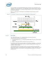
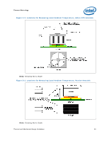
Thermal Metrology ΨSA is a measure of the thermal characterization parameter from the bottom of the heatsink to the local ambient air. ΨSA is dependent on the heatsink material, thermal conductivity, and geometry. It is also strongly dependent on the air velocity through the fins of the heatsink. Figure 3-1 illustrates the combination of the different thermal characterization parameters. Figure 3-1. Processor Thermal Characterization Parameter Relationships TA Heatsink TIM IHS Processor ΨCA TS TC LGA775 Socket System Board 3.1.1 Example The cooling performance, ΨCA, is defined using the principle of thermal characterization parameter described above: • The case temperature TC-MAX and thermal design power TDP given in the processor datasheet. • Define a target local ambient temperature at the processor, TA. Since the processor thermal profile applies to all processor frequencies, it is important to identify the worst case (lowest ΨCA) for a targeted chassis characterized by TA to establish a design strategy. The following provides an illustration of how one might determine the appropriate performance targets. The example power and temperature numbers used here are not related to any specific Intel processor thermal specifications, and are for illustrative purposes only. 26 Thermal and Mechanical Design Guidelines
-
 1
1 -
2
-
3
-
4
-
5
-
6
-
7
-
8
-
9
-
10
-
11
-
12
-
13
-
14
-
15
-
16
-
17
-
18
-
19
-
20
-
 21
21 -
 22
22 -
 23
23 -
 24
24 -
 25
25 -
 26
26 -
 27
27 -
 28
28 -
 29
29 -
 30
30 -
 31
31 -
32
-
33
-
34
-
35
-
36
-
37
-
38
-
39
-
40
-
41
-
42
-
43
-
44
-
45
-
46
-
47
-
48
-
49
-
50
-
51
-
52
-
53
-
54
-
55
-
56
-
57
-
58
-
59
-
60
-
61
-
62
-
63
-
64
-
65
-
66
-
67
-
68
-
69
-
70
-
71
-
72
-
73
-
74
-
75
-
76
-
77
-
78
-
79
-
80
-
81
-
82
-
83
-
84
-
85
-
86
-
87
-
88
-
89
-
90
-
91
-
92
-
93
-
94
-
95
-
96
-
97
-
98
-
99
-
100
-
101
-
102
-
103
-
104
-
105
-
106
-
107
-
108
-
109
-
110
-
111
-
112
-
113
-
114
-
115
-
116
-
117
-
118
-
119
-
120
-
121
-
122
-
123
-
124
-
125
-
126
 |
 |
