Intel E6700 Mechanical Design Guidelines - Page 17
Thermal Profile, Thermal Solution Design Requirements - core 2 duo 3 2
 |
UPC - 735858184618
View all Intel E6700 manuals
Add to My Manuals
Save this manual to your list of manuals |
Page 17 highlights
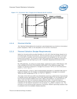
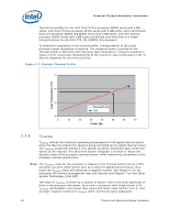
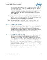
Processor Thermal/Mechanical Information Figure 2-2. Processor Case Temperature Measurement Location Measure TC at this point (geometric center of the package) 37.5 mm 37.5 mm 2.2.2 2.2.3 Thermal Profile The Thermal Profile defines the maximum case temperature as a function of processor power dissipation. Refer to the datasheet for the further information. Thermal Solution Design Requirements While the thermal profile provides flexibility for ATX /BTX thermal design based on its intended target thermal environment, thermal solutions that are intended to function in a multitude of systems and environments need to be designed for the worst-case thermal environment. The majority of ATX /BTX platforms are targeted to function in an environment that will have up to a 35 °C ambient temperature external to the system. For ATX platforms, an active air-cooled design, assumed be used in ATX Chassis, with a fan installed at the top of the heatsink equivalent to the reference design (see Chapter 6) should be designed to manage the processor TDP at an inlet temperature of 35 °C + 5°C = 40 °C. For BTX platforms, a front-to-back cooling design equivalent to Intel BTX TMA Type II reference design (see the Chapter 5) should be designed to manage the processor TDP at an inlet temperature of 35 °C + 0.5 °C = 35.5 °C. The slope of the thermal profile was established assuming a generational improvement in thermal solution performance of the Intel reference design. For an example of Intel Core™2 Duo processor E8000 series with 6 MB in ATX platform, its improvement is about 15% over the Intel reference design (E18764-001). This performance is expressed as the slope on the thermal profile and can be thought of as the thermal resistance of the heatsink attached to the processor, ΨCA (Refer to Section 3.1). The intercept on the thermal profile assumes a maximum ambient operating condition that is consistent with the available chassis solutions. Thermal and Mechanical Design Guidelines 17
-
 1
1 -
2
-
3
-
4
-
5
-
6
-
7
-
8
-
9
-
10
-
11
-
 12
12 -
 13
13 -
 14
14 -
 15
15 -
 16
16 -
 17
17 -
 18
18 -
 19
19 -
 20
20 -
 21
21 -
 22
22 -
23
-
24
-
25
-
26
-
27
-
28
-
29
-
30
-
31
-
32
-
33
-
34
-
35
-
36
-
37
-
38
-
39
-
40
-
41
-
42
-
43
-
44
-
45
-
46
-
47
-
48
-
49
-
50
-
51
-
52
-
53
-
54
-
55
-
56
-
57
-
58
-
59
-
60
-
61
-
62
-
63
-
64
-
65
-
66
-
67
-
68
-
69
-
70
-
71
-
72
-
73
-
74
-
75
-
76
-
77
-
78
-
79
-
80
-
81
-
82
-
83
-
84
-
85
-
86
-
87
-
88
-
89
-
90
-
91
-
92
-
93
-
94
-
95
-
96
-
97
-
98
-
99
-
100
-
101
-
102
-
103
-
104
-
105
-
106
-
107
-
108
-
109
-
110
-
111
-
112
-
113
-
114
-
115
-
116
-
117
-
118
-
119
-
120
-
121
-
122
-
123
-
124
-
125
-
126
 |
 |
