Intel E6700 Mechanical Design Guidelines - Page 18
Example Thermal Profile - pentium
 |
UPC - 735858184618
View all Intel E6700 manuals
Add to My Manuals
Save this manual to your list of manuals |
Page 18 highlights
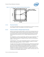
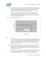
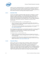
Processor Thermal/Mechanical Information The thermal profiles for the Intel Core™2 Duo processor E8000 series with 6 MB cache, Intel Core™2 Duo processor E7000 series with 3 MB cache, and Intel Pentium dual-core processor E6000 and E5000 series with 2 MB cache, and Intel Celeron processor E3000 series with 1 MB cache are defined such that there is a single thermal solution for all of the 775_VR_CONFIG_06 processors. To determine compliance to the thermal profile, a measurement of the actual processor power dissipation is required. The measured power is plotted on the Thermal Profile to determine the maximum case temperature. Using the example in Figure 2-3 for a processor dissipating 50 W the maximum case temperature is 58 °C. See the datasheet for the thermal profile. Figure 2-3. Example Thermal Profile 70 Case Temperature (°C) 60 50 Thermal Profile TDP 40 0 10 20 30 40 50 60 70 Power (W) 2.2.4 TCONTROL TCONTROL defines the maximum operating temperature for the digital thermal sensor when the thermal solution fan speed is being controlled by the digital thermal sensor. The TCONTROL parameter defines a very specific processor operating region where fan speed can be reduced. This allows the system integrator a method to reduce the acoustic noise of the processor cooling solution, while maintaining compliance to the processor thermal specification. Note: The TCONTROL value for the processor is relative to the Thermal Control Circuit (TCC) activation set point which will be seen as 0 using the digital thermal sensor. As a result the TCONTROL value will always be a negative number. See Chapter 4 for the discussion the thermal management logic and features and Chapter 7 on Intel Quiet System Technology (Intel QST). The value of TCONTROL is driven by a number of factors. One of the most significant of these is the processor idle power. As a result a processor with a high (closer to 0) TCONTROL will dissipate more power than a part with lower value (farther from 0, such as larger negative number) of TCONTROL when running the same application. 18 Thermal and Mechanical Design Guidelines
-
 1
1 -
2
-
3
-
4
-
5
-
6
-
7
-
8
-
9
-
10
-
11
-
12
-
 13
13 -
 14
14 -
 15
15 -
 16
16 -
 17
17 -
 18
18 -
 19
19 -
 20
20 -
 21
21 -
 22
22 -
 23
23 -
24
-
25
-
26
-
27
-
28
-
29
-
30
-
31
-
32
-
33
-
34
-
35
-
36
-
37
-
38
-
39
-
40
-
41
-
42
-
43
-
44
-
45
-
46
-
47
-
48
-
49
-
50
-
51
-
52
-
53
-
54
-
55
-
56
-
57
-
58
-
59
-
60
-
61
-
62
-
63
-
64
-
65
-
66
-
67
-
68
-
69
-
70
-
71
-
72
-
73
-
74
-
75
-
76
-
77
-
78
-
79
-
80
-
81
-
82
-
83
-
84
-
85
-
86
-
87
-
88
-
89
-
90
-
91
-
92
-
93
-
94
-
95
-
96
-
97
-
98
-
99
-
100
-
101
-
102
-
103
-
104
-
105
-
106
-
107
-
108
-
109
-
110
-
111
-
112
-
113
-
114
-
115
-
116
-
117
-
118
-
119
-
120
-
121
-
122
-
123
-
124
-
125
-
126
 |
 |
