Intel E6700 Mechanical Design Guidelines - Page 27
Processor Thermal Solution Performance, Assessment, Local Ambient Temperature Measurement,
 |
UPC - 735858184618
View all Intel E6700 manuals
Add to My Manuals
Save this manual to your list of manuals |
Page 27 highlights
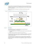
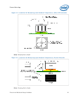
Thermal Metrology 3.2 3.3 Assume the TDP, as listed in the datasheet, is 100 W and the maximum case temperature from the thermal profile for 100 W is 67 °C. Assume as well that the system airflow has been designed such that the local ambient temperature is 38 °C. Then, the following could be calculated using equation 1 from above: ΨCA = (TC, − TA) / TDP = (67 - 38) / 100 = 0.29 °C/W To determine the required heatsink performance, a heatsink solution provider would need to determine ΨCS performance for the selected TIM and mechanical load configuration. If the heatsink solution were designed to work with a TIM material performing at ΨCS ≤ 0.10 °C/W, solving for equation 2 from above, the performance of the heatsink would be: ΨSA = ΨCA − ΨCS = 0.29 − 0.10 = 0.19 °C/W Processor Thermal Solution Performance Assessment Thermal performance of a heatsink should be assessed using a thermal test vehicle (TTV) provided by Intel. The TTV is a stable heat source that the user can make accurate power measurement, whereas processors can introduce additional factors that can impact test results. In particular, the power level from actual processors varies significantly, even when running the maximum power application provided by Intel, due to variances in the manufacturing process. The TTV provides consistent power and power density for thermal solution characterization and results can be easily translated to real processor performance. Accurate measurement of the power dissipated by an actual processor is beyond the scope of this document. Once the thermal solution is designed and validated with the TTV, it is strongly recommended to verify functionality of the thermal solution on real processors and on fully integrated systems. The Intel maximum power application enables steady power dissipation on a processor to assist in this testing. This maximum power application is provided by Intel. Local Ambient Temperature Measurement Guidelines The local ambient temperature TA is the temperature of the ambient air surrounding the processor. For a passive heatsink, TA is defined as the heatsink approach air temperature; for an actively cooled heatsink, it is the temperature of inlet air to the active cooling fan. It is worthwhile to determine the local ambient temperature in the chassis around the processor to understand the effect it may have on the case temperature. TA is best measured by averaging temperature measurements at multiple locations in the heatsink inlet airflow. This method helps reduce error and eliminate minor spatial variations in temperature. The following guidelines are meant to enable accurate determination of the localized air temperature around the processor during system thermal testing. Thermal and Mechanical Design Guidelines 27
-
 1
1 -
2
-
3
-
4
-
5
-
6
-
7
-
8
-
9
-
10
-
11
-
12
-
13
-
14
-
15
-
16
-
17
-
18
-
19
-
20
-
21
-
 22
22 -
 23
23 -
 24
24 -
 25
25 -
 26
26 -
 27
27 -
 28
28 -
 29
29 -
 30
30 -
 31
31 -
 32
32 -
33
-
34
-
35
-
36
-
37
-
38
-
39
-
40
-
41
-
42
-
43
-
44
-
45
-
46
-
47
-
48
-
49
-
50
-
51
-
52
-
53
-
54
-
55
-
56
-
57
-
58
-
59
-
60
-
61
-
62
-
63
-
64
-
65
-
66
-
67
-
68
-
69
-
70
-
71
-
72
-
73
-
74
-
75
-
76
-
77
-
78
-
79
-
80
-
81
-
82
-
83
-
84
-
85
-
86
-
87
-
88
-
89
-
90
-
91
-
92
-
93
-
94
-
95
-
96
-
97
-
98
-
99
-
100
-
101
-
102
-
103
-
104
-
105
-
106
-
107
-
108
-
109
-
110
-
111
-
112
-
113
-
114
-
115
-
116
-
117
-
118
-
119
-
120
-
121
-
122
-
123
-
124
-
125
-
126
 |
 |
