LG PQCPA11A0E Owner's Manual - Page 22
Setting the indoor unit address
 |
View all LG PQCPA11A0E manuals
Add to My Manuals
Save this manual to your list of manuals |
Page 22 highlights
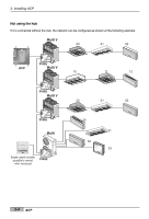
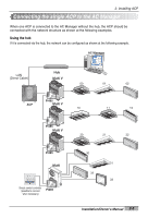
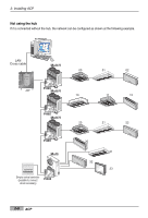
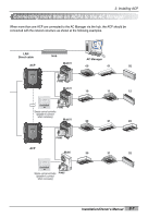
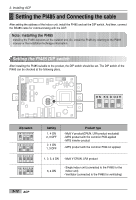
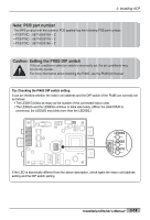
2. Installing ACP Setting the indoor unit address By considering the entire installation configuration connecting to one ACP, set the address to each indoor unit not to be overlapped. 00~FF in hexadecimal can be set to the indoor unit address. The following example sets the address to the indoor unit. Multi V 00 01 02 1 DI 2 3 4 5 6 7 8 9 10 11 12 13 14 15 16 17 18 19 20 MENU/ SELECT 1 DO 2 3 4 LG-NET 1 TX RX LG-NET 2 TX RX LG-NET 3 TX RX LG-NET 4 TX RX FDD TX RX Ext. TX RX Ethernet 1 ACT LNK Ethernet 2 ACT LNK Console TX RX Run Power ACP ON KSDO4H L1 2 3 4 PI485 Multi 10 11 12 ON KSDO4H L1 2 3 4 ON KSDO4H L1 2 3 4 ON KSDO4H L1 2 3 4 Ventilator 30 PI485 Ventilator 31 PI485 When the ACP is interconnected with the AC Manager, the ventilator can be together installed and controlled. The above figure shows the example that sets 30 and 31 to the ventilators as address and connects to the ACP. Caution: Connecting the ventilator to the RS485 The ventilator and the air conditioner can not be connected together to the same RS485 communication cable. When connecting the ventilator to the RS485 communication cable, the cable other than the RS485 communication cable connecting the air conditioner should be used. The next section describes how to set the address to each indoor unit by using the wired or wireless remote controller according to the given number. 2-8 ACP
-
 1
1 -
2
-
3
-
4
-
5
-
6
-
7
-
8
-
9
-
10
-
11
-
12
-
13
-
14
-
15
-
16
-
 17
17 -
 18
18 -
 19
19 -
 20
20 -
 21
21 -
 22
22 -
 23
23 -
 24
24 -
 25
25 -
 26
26 -
 27
27 -
28
-
29
-
30
-
31
-
32
-
33
-
34
-
35
-
36
-
37
-
38
-
39
-
40
-
41
-
42
-
43
-
44
-
45
-
46
-
47
-
48
-
49
-
50
-
51
-
52
-
53
-
54
-
55
-
56
-
57
-
58
-
59
-
60
-
61
-
62
-
63
-
64
-
65
-
66
-
67
-
68
-
69
-
70
-
71
-
72
-
73
-
74
-
75
-
76
-
77
-
78
-
79
-
80
-
81
-
82
-
83
-
84
-
85
-
86
-
87
-
88
-
89
-
90
-
91
-
92
-
93
-
94
-
95
-
96
-
97
-
98
-
99
-
100
-
101
-
102
-
103
-
104
-
105
-
106
-
107
-
108
-
109
-
110
-
111
-
112
-
113
-
114
-
115
-
116
-
117
-
118
-
119
-
120
-
121
-
122
-
123
-
124
-
125
-
126
-
127
-
128
-
129
-
130
-
131
-
132
-
133
-
134
-
135
-
136
-
137
-
138
-
139
-
140
-
141
-
142
-
143
-
144
-
145
-
146
-
147
-
148
-
149
-
150
-
151
-
152
-
153
-
154
-
155
-
156
-
157
-
158
-
159
-
160
-
161
-
162
-
163
 |
 |
