LG PQCPA11A0E Owner's Manual - Page 34
Connecting RS485 cable to ACP
 |
View all LG PQCPA11A0E manuals
Add to My Manuals
Save this manual to your list of manuals |
Page 34 highlights
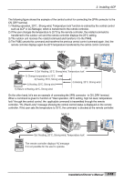
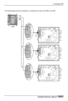
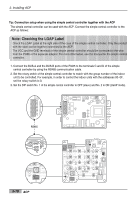
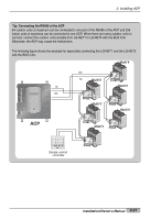
2. Installing ACP Connecting RS485 cable to ACP After fixing the ACP at the installation place, the RS485 cable connecting the PI485 to the ACP. Connect the RS485 cable to the ACP as follows: 1. The end of the RS485 cable connecting to the BUS_A of the PI485 of the connector possible to be connected to the ACP to the TX. Next, connect the end of the RS485 cable connecting to the BUS_B of the PI485 to the RX. RS485 - TX RS485 - RX Caution: Connecting the RS485 communication cable Because the connection of the RS485 communication cable has a polarity, be careful that the connection of two cables is not changed. 2. The RS485 cable connecting to the PI485 to the LG-NET port (RS485 port) of the ACP. Connect the connector connecting the RS485 cable to one of the ports LG-NET1~LG-NET4. The number of LG-NET ports is 1~4 and it is possible to connect to any of them to use. 2-20 ACP 1 2 DI 3 4 5 6 7 8 9 10 11 12 13 14 15 16 17 18 19 20 SMEELNEUC/T 1 2 DO 3 4 LG-NET 1 TX LG-NET 2 RX TX LG-NET 3 RX TX LG-NET 4 RX TX RX FDD TX Ext. RX TX RX Ethernet 1 ACT LNK Ethernet 2 ACT LNK Console TX RX Run Power
-
 1
1 -
2
-
3
-
4
-
5
-
6
-
7
-
8
-
9
-
10
-
11
-
12
-
13
-
14
-
15
-
16
-
17
-
18
-
19
-
20
-
21
-
22
-
23
-
24
-
25
-
26
-
27
-
28
-
 29
29 -
 30
30 -
 31
31 -
 32
32 -
 33
33 -
 34
34 -
 35
35 -
 36
36 -
 37
37 -
 38
38 -
 39
39 -
40
-
41
-
42
-
43
-
44
-
45
-
46
-
47
-
48
-
49
-
50
-
51
-
52
-
53
-
54
-
55
-
56
-
57
-
58
-
59
-
60
-
61
-
62
-
63
-
64
-
65
-
66
-
67
-
68
-
69
-
70
-
71
-
72
-
73
-
74
-
75
-
76
-
77
-
78
-
79
-
80
-
81
-
82
-
83
-
84
-
85
-
86
-
87
-
88
-
89
-
90
-
91
-
92
-
93
-
94
-
95
-
96
-
97
-
98
-
99
-
100
-
101
-
102
-
103
-
104
-
105
-
106
-
107
-
108
-
109
-
110
-
111
-
112
-
113
-
114
-
115
-
116
-
117
-
118
-
119
-
120
-
121
-
122
-
123
-
124
-
125
-
126
-
127
-
128
-
129
-
130
-
131
-
132
-
133
-
134
-
135
-
136
-
137
-
138
-
139
-
140
-
141
-
142
-
143
-
144
-
145
-
146
-
147
-
148
-
149
-
150
-
151
-
152
-
153
-
154
-
155
-
156
-
157
-
158
-
159
-
160
-
161
-
162
-
163
 |
 |
