LG PQCPA11A0E Owner's Manual - Page 26
Setting the PI485 and Connecting the cable
 |
View all LG PQCPA11A0E manuals
Add to My Manuals
Save this manual to your list of manuals |
Page 26 highlights
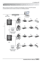
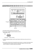
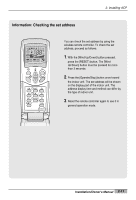
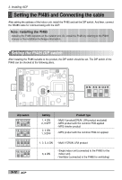
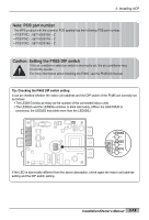
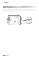
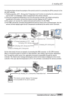
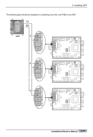
2. Installing ACP Setting the PI485 and Connecting the cable After setting the address of the indoor unit, install the PI485 and set the DIP switch. And then, connect the RS485 cable for communicating with the ACP. Note: Installing the PI485 Installing the PI485 deponds on the outdoor unit. So, install the PI485 by referring to the PI485 manual or the installation technique information. Setting the PI485 DIP switch After installing the PI485 suitable to the product, the DIP switch should be set. The DIP switch of the PI485 can be checked at the following place. ON KS D O4H ON KSDO4H L1 2 3 4 Dip switch ON KS D O4H ON KS D O4H ON KS D O4H ON KS D O4H Setting 1, 4 ON 2, 3 OFF 2, 4 ON 1, 3 OFF Product type - Multi V product(CRUN, LRA product excluded) - MPS product with the common PCB applied - MPS inverter product - MPS product with the common PCB not applied 1, 2, 3, 4 ON - Multi V CRUN, LRA product 3, 4 ON - Single indoor unit (connected to the PI485 for the indoor unit) - Ventilator (connected to the PI485 for ventilating) 2-12 ACP
-
 1
1 -
2
-
3
-
4
-
5
-
6
-
7
-
8
-
9
-
10
-
11
-
12
-
13
-
14
-
15
-
16
-
17
-
18
-
19
-
20
-
 21
21 -
 22
22 -
 23
23 -
 24
24 -
 25
25 -
 26
26 -
 27
27 -
 28
28 -
 29
29 -
 30
30 -
 31
31 -
32
-
33
-
34
-
35
-
36
-
37
-
38
-
39
-
40
-
41
-
42
-
43
-
44
-
45
-
46
-
47
-
48
-
49
-
50
-
51
-
52
-
53
-
54
-
55
-
56
-
57
-
58
-
59
-
60
-
61
-
62
-
63
-
64
-
65
-
66
-
67
-
68
-
69
-
70
-
71
-
72
-
73
-
74
-
75
-
76
-
77
-
78
-
79
-
80
-
81
-
82
-
83
-
84
-
85
-
86
-
87
-
88
-
89
-
90
-
91
-
92
-
93
-
94
-
95
-
96
-
97
-
98
-
99
-
100
-
101
-
102
-
103
-
104
-
105
-
106
-
107
-
108
-
109
-
110
-
111
-
112
-
113
-
114
-
115
-
116
-
117
-
118
-
119
-
120
-
121
-
122
-
123
-
124
-
125
-
126
-
127
-
128
-
129
-
130
-
131
-
132
-
133
-
134
-
135
-
136
-
137
-
138
-
139
-
140
-
141
-
142
-
143
-
144
-
145
-
146
-
147
-
148
-
149
-
150
-
151
-
152
-
153
-
154
-
155
-
156
-
157
-
158
-
159
-
160
-
161
-
162
-
163
 |
 |
