Lexmark T642 Service Manual - Page 120
Cover closed switch/cable service check, Dead machine service check, Cover closed switch table
 |
UPC - 734646722001
View all Lexmark T642 manuals
Add to My Manuals
Save this manual to your list of manuals |
Page 120 highlights
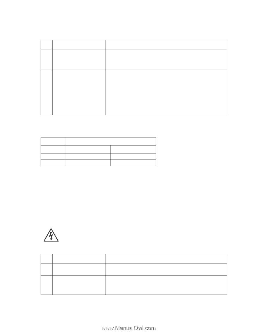
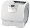
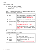
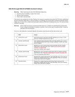
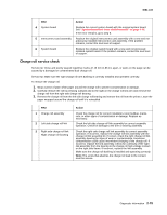
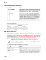
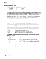
4061-xx0 Cover closed switch/cable service check FRU 1 Toner cartridge 2 Cover closed switch/cable assembly Action Make sure the toner cartridge is correctly installed and that the right and left cartridge tracks are not loose or broken. Make sure the cover closed switch activation tab on the toner cartridge is not broken and that the tab correctly activates the cover closed switch spring. Check the cover closed switch for proper mechanical operation. If incorrect, repair as necessary. Disconnect the cover closed switch cable from J8 at the system board and measure the voltage at J8-3. It measures approximately +5 V dc. If the voltage is incorrect, replace the system board. If the voltage is correct, check the voltage at J8-1. If the voltage measures greater than +1.0 V dc, replace the system board. If the voltage is correct, check the continuity between J8-1 and J8-3 on the cable. If no change in continuity occurs as the switch is activated, replace the cover open switch/cable assembly. If the continuity changes as the switch is activated, replace the system board. Cover closed switch table J8 Switch status Pin number Pin 1-3 Pin 1-2 Cover open Open Closed Cover closed Closed Open Dead machine service check A dead machine is a condition where the display is blank, the LED on the operator panel is off, no fans turn, no motors turn, and the fuser lamp does not come on. If a high-capacity input tray is installed, remove the option and check the base printer for correct operation. If the base printer operates correctly, go to "High-capacity feeder input tray service check" on page 2-95. If the base printer continues to not operate correctly, remove any other attached paper handling options. Warning: Observe all necessary ESD precautions when removing and handling the system board or any installed option cards or assemblies. See "Handling ESD-sensitive parts" on page 4-1. CAUTION: When you see this symbol, there is a danger from hazardous voltage in the area of the printer where you are working. Unplug the printer before you begin, or use caution if the printer must receive power in order to perform the task. Remove any input and output paper handling options from the printer. FRU 1 Line voltage 2 AC line cord Action Check the AC line voltage. If the line voltage is incorrect, inform the customer. Unplug the line cord from the wall outlet and check the line cord for damage, such as, a damaged plug, or cut or damaged cord. If incorrect, replace the cord. If incorrect, check the continuity of the line cord and replace if necessary. If the cord is correct, go to step 3. 2-80 Service Manual
-
 1
1 -
2
-
3
-
4
-
5
-
6
-
7
-
8
-
9
-
10
-
11
-
12
-
13
-
14
-
15
-
16
-
17
-
18
-
19
-
20
-
21
-
22
-
23
-
24
-
25
-
26
-
27
-
28
-
29
-
30
-
31
-
32
-
33
-
34
-
35
-
36
-
37
-
38
-
39
-
40
-
41
-
42
-
43
-
44
-
45
-
46
-
47
-
48
-
49
-
50
-
51
-
52
-
53
-
54
-
55
-
56
-
57
-
58
-
59
-
60
-
61
-
62
-
63
-
64
-
65
-
66
-
67
-
68
-
69
-
70
-
71
-
72
-
73
-
74
-
75
-
76
-
77
-
78
-
79
-
80
-
81
-
82
-
83
-
84
-
85
-
86
-
87
-
88
-
89
-
90
-
91
-
92
-
93
-
94
-
95
-
96
-
97
-
98
-
99
-
100
-
101
-
102
-
103
-
104
-
105
-
106
-
107
-
108
-
109
-
110
-
111
-
112
-
113
-
114
-
 115
115 -
 116
116 -
 117
117 -
 118
118 -
 119
119 -
 120
120 -
 121
121 -
 122
122 -
 123
123 -
 124
124 -
 125
125 -
126
-
127
-
128
-
129
-
130
-
131
-
132
-
133
-
134
-
135
-
136
-
137
-
138
-
139
-
140
-
141
-
142
-
143
-
144
-
145
-
146
-
147
-
148
-
149
-
150
-
151
-
152
-
153
-
154
-
155
-
156
-
157
-
158
-
159
-
160
-
161
-
162
-
163
-
164
-
165
-
166
-
167
-
168
-
169
-
170
-
171
-
172
-
173
-
174
-
175
-
176
-
177
-
178
-
179
-
180
-
181
-
182
-
183
-
184
-
185
-
186
-
187
-
188
-
189
-
190
-
191
-
192
-
193
-
194
-
195
-
196
-
197
-
198
-
199
-
200
-
201
-
202
-
203
-
204
-
205
-
206
-
207
-
208
-
209
-
210
-
211
-
212
-
213
-
214
-
215
-
216
-
217
-
218
-
219
-
220
-
221
-
222
-
223
-
224
-
225
-
226
-
227
-
228
-
229
-
230
-
231
-
232
-
233
-
234
-
235
-
236
-
237
-
238
-
239
-
240
-
241
-
242
-
243
-
244
-
245
-
246
-
247
-
248
-
249
-
250
-
251
-
252
-
253
-
254
-
255
-
256
-
257
-
258
-
259
-
260
-
261
-
262
-
263
-
264
-
265
-
266
-
267
-
268
-
269
-
270
-
271
-
272
-
273
-
274
-
275
-
276
-
277
-
278
-
279
-
280
-
281
-
282
-
283
-
284
-
285
-
286
-
287
-
288
-
289
-
290
-
291
-
292
-
293
-
294
-
295
-
296
-
297
-
298
-
299
-
300
-
301
-
302
-
303
-
304
-
305
-
306
-
307
-
308
-
309
-
310
-
311
-
312
-
313
-
314
-
315
-
316
-
317
-
318
-
319
-
320
-
321
-
322
-
323
-
324
-
325
-
326
-
327
-
328
-
329
-
330
-
331
-
332
-
333
-
334
-
335
-
336
-
337
-
338
-
339
-
340
-
341
-
342
-
343
-
344
-
345
-
346
-
347
-
348
-
349
-
350
-
351
-
352
-
353
-
354
-
355
-
356
-
357
-
358
-
359
-
360
-
361
-
362
-
363
-
364
-
365
-
366
-
367
-
368
-
369
-
370
-
371
-
372
-
373
-
374
-
375
-
376
-
377
-
378
-
379
-
380
-
381
-
382
-
383
-
384
-
385
-
386
-
387
-
388
-
389
-
390
-
391
-
392
-
393
-
394
-
395
-
396
-
397
-
398
-
399
-
400
-
401
-
402
-
403
-
404
-
405
-
406
-
407
-
408
-
409
-
410
-
411
-
412
-
413
-
414
-
415
-
416
-
417
-
418
-
419
-
420
-
421
-
422
 |
 |