Lexmark T642 Service Manual - Page 85
User attendance messages-paper jams and paper handling errors 2, xx.xx - fuser assembly
 |
UPC - 734646722001
View all Lexmark T642 manuals
Add to My Manuals
Save this manual to your list of manuals |
Page 85 highlights
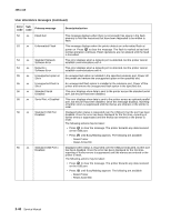
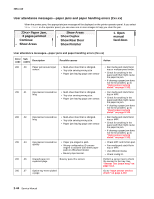
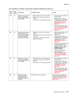
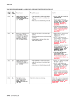
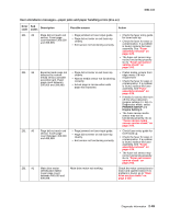
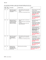
4061-xx0 User attendance messages-paper jams and paper handling errors (2xx.xx) Error code Sub codes Description Possible causes Action 200 .08 200 .09 200 .10 200 .11 200 .13 200 .16 200 .32 201 .00 201 .01 Input sensor covered too quickly • Paper pre-staged in path. • Bouncy input sensor. Did not receive proper motor feedback to start laser servo. Motor connections Printhead motor not locked when page crosses input sensor • Printhead lock signal not working. • Printhead control not working. Printhead motor fell out of lock after page arrives at input sensor • Paper pre-staged in path. • Lock signal went away. Input sensor covered during warm-up sequence. Page still covering input sensor. Main drive motor error possibly due to mechanical load. Main drive motor not working. Detected cover switch bounce. • Upper cover not fully closed. • Cover switch not functioning correctly. Page did not reach exit sensor. Fuser page count between 0 and 99,999. • Page jammed on fuser input guide. • Page did not enter or exit fuser nip cleanly. • Exit sensor not functioning correctly. Main drive motor identification failed. Fuser page count between 0 and 99,999. Main drive motor not working. • Check MPF and friction pad. • Fan media and stack flat in tray or MPF. • Use different media. Check the main drive motor cable connections. If no problem is found with motor connections, go to "Main drive service check" on page 2-105. Go to "Printhead service check" on page 2-122. Go to "Printhead service check" on page 2-122. Go to "Input sensor service check" on page 2-102. Go to "Main drive service check" on page 2-105. Go to "Cover closed switch/ cable service check" on page 2-80. • Check fuser entry guide for toner build up. • Check fuser for wear or contamination. If problem is found, replace the fuser assembly. See "Fuser assembly removal" on page 4-26. • The fuser exit sensor may not be functioning properly. Go to "Fuser exit sensor service check" on page 2-92. Check motor connections to motor and system board. If no problem is found, go to "Main drive service check" on page 2-105. Diagnostic information 2-45
-
 1
1 -
2
-
3
-
4
-
5
-
6
-
7
-
8
-
9
-
10
-
11
-
12
-
13
-
14
-
15
-
16
-
17
-
18
-
19
-
20
-
21
-
22
-
23
-
24
-
25
-
26
-
27
-
28
-
29
-
30
-
31
-
32
-
33
-
34
-
35
-
36
-
37
-
38
-
39
-
40
-
41
-
42
-
43
-
44
-
45
-
46
-
47
-
48
-
49
-
50
-
51
-
52
-
53
-
54
-
55
-
56
-
57
-
58
-
59
-
60
-
61
-
62
-
63
-
64
-
65
-
66
-
67
-
68
-
69
-
70
-
71
-
72
-
73
-
74
-
75
-
76
-
77
-
78
-
79
-
 80
80 -
 81
81 -
 82
82 -
 83
83 -
 84
84 -
 85
85 -
 86
86 -
 87
87 -
 88
88 -
 89
89 -
 90
90 -
91
-
92
-
93
-
94
-
95
-
96
-
97
-
98
-
99
-
100
-
101
-
102
-
103
-
104
-
105
-
106
-
107
-
108
-
109
-
110
-
111
-
112
-
113
-
114
-
115
-
116
-
117
-
118
-
119
-
120
-
121
-
122
-
123
-
124
-
125
-
126
-
127
-
128
-
129
-
130
-
131
-
132
-
133
-
134
-
135
-
136
-
137
-
138
-
139
-
140
-
141
-
142
-
143
-
144
-
145
-
146
-
147
-
148
-
149
-
150
-
151
-
152
-
153
-
154
-
155
-
156
-
157
-
158
-
159
-
160
-
161
-
162
-
163
-
164
-
165
-
166
-
167
-
168
-
169
-
170
-
171
-
172
-
173
-
174
-
175
-
176
-
177
-
178
-
179
-
180
-
181
-
182
-
183
-
184
-
185
-
186
-
187
-
188
-
189
-
190
-
191
-
192
-
193
-
194
-
195
-
196
-
197
-
198
-
199
-
200
-
201
-
202
-
203
-
204
-
205
-
206
-
207
-
208
-
209
-
210
-
211
-
212
-
213
-
214
-
215
-
216
-
217
-
218
-
219
-
220
-
221
-
222
-
223
-
224
-
225
-
226
-
227
-
228
-
229
-
230
-
231
-
232
-
233
-
234
-
235
-
236
-
237
-
238
-
239
-
240
-
241
-
242
-
243
-
244
-
245
-
246
-
247
-
248
-
249
-
250
-
251
-
252
-
253
-
254
-
255
-
256
-
257
-
258
-
259
-
260
-
261
-
262
-
263
-
264
-
265
-
266
-
267
-
268
-
269
-
270
-
271
-
272
-
273
-
274
-
275
-
276
-
277
-
278
-
279
-
280
-
281
-
282
-
283
-
284
-
285
-
286
-
287
-
288
-
289
-
290
-
291
-
292
-
293
-
294
-
295
-
296
-
297
-
298
-
299
-
300
-
301
-
302
-
303
-
304
-
305
-
306
-
307
-
308
-
309
-
310
-
311
-
312
-
313
-
314
-
315
-
316
-
317
-
318
-
319
-
320
-
321
-
322
-
323
-
324
-
325
-
326
-
327
-
328
-
329
-
330
-
331
-
332
-
333
-
334
-
335
-
336
-
337
-
338
-
339
-
340
-
341
-
342
-
343
-
344
-
345
-
346
-
347
-
348
-
349
-
350
-
351
-
352
-
353
-
354
-
355
-
356
-
357
-
358
-
359
-
360
-
361
-
362
-
363
-
364
-
365
-
366
-
367
-
368
-
369
-
370
-
371
-
372
-
373
-
374
-
375
-
376
-
377
-
378
-
379
-
380
-
381
-
382
-
383
-
384
-
385
-
386
-
387
-
388
-
389
-
390
-
391
-
392
-
393
-
394
-
395
-
396
-
397
-
398
-
399
-
400
-
401
-
402
-
403
-
404
-
405
-
406
-
407
-
408
-
409
-
410
-
411
-
412
-
413
-
414
-
415
-
416
-
417
-
418
-
419
-
420
-
421
-
422
 |
 |