Lexmark T642 Service Manual - Page 140
High-capacity output stacker service check
 |
UPC - 734646722001
View all Lexmark T642 manuals
Add to My Manuals
Save this manual to your list of manuals |
Page 140 highlights
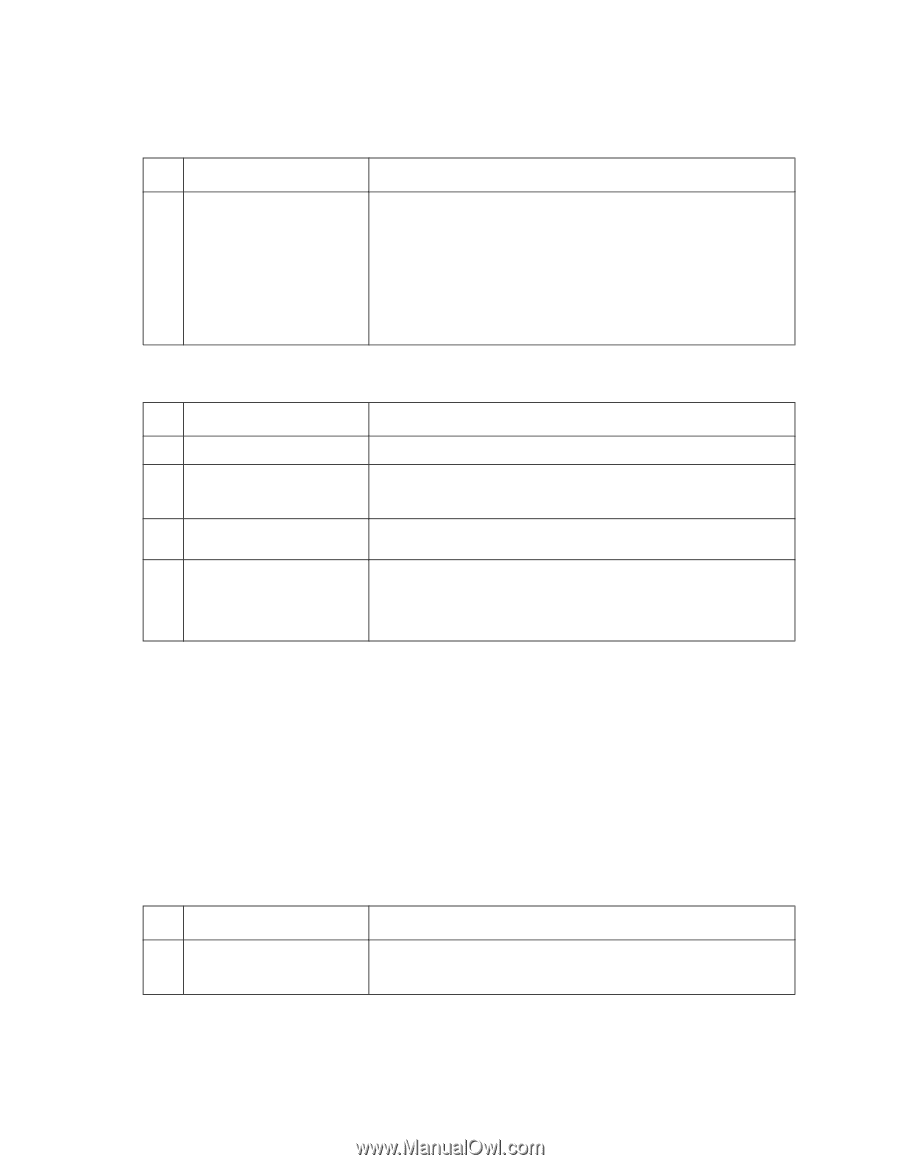
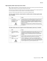
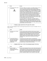
4061-xx0 Tray x Paper Low displays when the high-capacity feeder input tray is full or has adequate paper in the tray FRU 1 Paper low switch Paper low switch cable High-capacity feeder option control board Action Run the sensor diagnostics for tray x (x=the number that represents the high-capacity input tray). If the test fails, check the voltage at J3-1 (gray). The voltage measures approximately +24 V dc. If incorrect, disconnect the paper low switch cable from J3 and measure the voltage again on J3-1. If incorrect, replace the high-capacity feeder option control board. If correct, check the cable for a short between pins 1 and 2 on the cable. If incorrect, replace the cable. If correct, check the switch for a bent or deformed actuator lever or defective switch. If incorrect, replace the switch. Excessive noise or vibration FRU 1 DC motor assembly 2 Idler pulley DC motor assembly 3 Drive pulley 4 Motor drive belt tray drive belt Action Make sure all the motor plate mounting screws are tight. Make sure the idler pulley is not binding on the pulley shaft. Check the pulley for wear. Check the idler pulley shaft on the motor mounting plate for damage or contamination. Check the drive pulley for wear, binds or damage to the pulley or pulley shaft. Make sure the pulley turns freely on the pulley shaft. Check the DC motor drive belt for damage. Make sure the belt is tracking correctly on the drive pulley, idler pulley, and motor pulley. Check the tray drive belt for damage. Make sure the belt is tracking correctly on the lower section of the drive pulley and lead screw pulleys. High-capacity output stacker service check Service tip: The majority of the mechanical components can be observed during operation by removing the left, right, and front covers. The high-capacity output stacker option functions without the covers installed. Determine which paper path stacker assembly is not functioning properly. Make sure the option(s) are installed correctly and the machine is configured correctly before attempting to service the high-capacity output stacker option. See "High-capacity output stacker board" on page 5-8 to identify the correct jumper locations at J6 for the upper and lower units. Problems with excessive static electricity buildup FRU 1 Front Cover Assembly Action Check the front cover assembly to make sure the ESD brush ground lead is firmly attached to the high-capacity option. Also check to make sure the ESD brush is not loose or damaged. 2-100 Service Manual
-
 1
1 -
2
-
3
-
4
-
5
-
6
-
7
-
8
-
9
-
10
-
11
-
12
-
13
-
14
-
15
-
16
-
17
-
18
-
19
-
20
-
21
-
22
-
23
-
24
-
25
-
26
-
27
-
28
-
29
-
30
-
31
-
32
-
33
-
34
-
35
-
36
-
37
-
38
-
39
-
40
-
41
-
42
-
43
-
44
-
45
-
46
-
47
-
48
-
49
-
50
-
51
-
52
-
53
-
54
-
55
-
56
-
57
-
58
-
59
-
60
-
61
-
62
-
63
-
64
-
65
-
66
-
67
-
68
-
69
-
70
-
71
-
72
-
73
-
74
-
75
-
76
-
77
-
78
-
79
-
80
-
81
-
82
-
83
-
84
-
85
-
86
-
87
-
88
-
89
-
90
-
91
-
92
-
93
-
94
-
95
-
96
-
97
-
98
-
99
-
100
-
101
-
102
-
103
-
104
-
105
-
106
-
107
-
108
-
109
-
110
-
111
-
112
-
113
-
114
-
115
-
116
-
117
-
118
-
119
-
120
-
121
-
122
-
123
-
124
-
125
-
126
-
127
-
128
-
129
-
130
-
131
-
132
-
133
-
134
-
 135
135 -
 136
136 -
 137
137 -
 138
138 -
 139
139 -
 140
140 -
 141
141 -
 142
142 -
 143
143 -
 144
144 -
 145
145 -
146
-
147
-
148
-
149
-
150
-
151
-
152
-
153
-
154
-
155
-
156
-
157
-
158
-
159
-
160
-
161
-
162
-
163
-
164
-
165
-
166
-
167
-
168
-
169
-
170
-
171
-
172
-
173
-
174
-
175
-
176
-
177
-
178
-
179
-
180
-
181
-
182
-
183
-
184
-
185
-
186
-
187
-
188
-
189
-
190
-
191
-
192
-
193
-
194
-
195
-
196
-
197
-
198
-
199
-
200
-
201
-
202
-
203
-
204
-
205
-
206
-
207
-
208
-
209
-
210
-
211
-
212
-
213
-
214
-
215
-
216
-
217
-
218
-
219
-
220
-
221
-
222
-
223
-
224
-
225
-
226
-
227
-
228
-
229
-
230
-
231
-
232
-
233
-
234
-
235
-
236
-
237
-
238
-
239
-
240
-
241
-
242
-
243
-
244
-
245
-
246
-
247
-
248
-
249
-
250
-
251
-
252
-
253
-
254
-
255
-
256
-
257
-
258
-
259
-
260
-
261
-
262
-
263
-
264
-
265
-
266
-
267
-
268
-
269
-
270
-
271
-
272
-
273
-
274
-
275
-
276
-
277
-
278
-
279
-
280
-
281
-
282
-
283
-
284
-
285
-
286
-
287
-
288
-
289
-
290
-
291
-
292
-
293
-
294
-
295
-
296
-
297
-
298
-
299
-
300
-
301
-
302
-
303
-
304
-
305
-
306
-
307
-
308
-
309
-
310
-
311
-
312
-
313
-
314
-
315
-
316
-
317
-
318
-
319
-
320
-
321
-
322
-
323
-
324
-
325
-
326
-
327
-
328
-
329
-
330
-
331
-
332
-
333
-
334
-
335
-
336
-
337
-
338
-
339
-
340
-
341
-
342
-
343
-
344
-
345
-
346
-
347
-
348
-
349
-
350
-
351
-
352
-
353
-
354
-
355
-
356
-
357
-
358
-
359
-
360
-
361
-
362
-
363
-
364
-
365
-
366
-
367
-
368
-
369
-
370
-
371
-
372
-
373
-
374
-
375
-
376
-
377
-
378
-
379
-
380
-
381
-
382
-
383
-
384
-
385
-
386
-
387
-
388
-
389
-
390
-
391
-
392
-
393
-
394
-
395
-
396
-
397
-
398
-
399
-
400
-
401
-
402
-
403
-
404
-
405
-
406
-
407
-
408
-
409
-
410
-
411
-
412
-
413
-
414
-
415
-
416
-
417
-
418
-
419
-
420
-
421
-
422
 |
 |