Lexmark T642 Service Manual - Page 128
CAUTION, Fuser assembly. See
 |
UPC - 734646722001
View all Lexmark T642 manuals
Add to My Manuals
Save this manual to your list of manuals |
Page 128 highlights
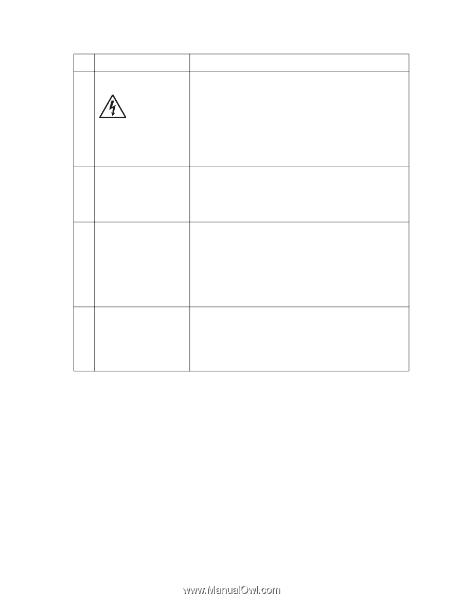
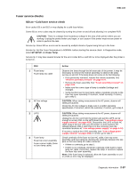
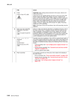
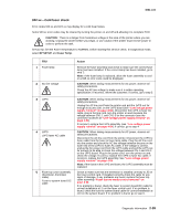
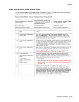
4061-xx0 FRU 5 LVPS LVPS to fuser AC cable 6 Fuser top cover assembly (thermistor, thermistor cable) Fuser to system board DC cable 7 Error code 920.06 displayed LVPS System board System board to LVPS cable 8 Fuser assembly Action CAUTION: When taking measurements for AC power, observe all safety precautions. Check the AC line voltage between the pins on the fuser end of the LPVS to fuser AC cable. If the voltage is correct, unplug the AC power cord from the LVPS cable. If the voltage is correct, unplug the AC power cord from the LVPS, pull the LVPS out far enough to be able to check the voltage between CN-1 and CN1-3 on the LVPS board. Plug in the power cord, turn the printer on and check the voltage. If correct, replace the LVPS to fuser AC cable; if incorrect, replace the LVPS assembly. Note: If the fuses in the LVPS are blown, the LVPS assembly must be replaced. Check to make sure that the thermistor is installed correctly to J5 on the fuser control card. If installed correctly check the cable for any signs of damage. If any problems are found, replace the fuser top cover assembly. If no problem is found, check the fuser to system board DC cable for correct installation at J1 on the fuser control card. If no problem is found, check the fuser to system board cable for correct installation at J10 on the system board. Carefully check the installation of the LVPS to system board cable to J27 on the system board and to CN2 on the LVPS. If the cable is not seated or installed properly, reseat the cable and retry the printer. If the cable is installed correctly, replace the following FRUs in the order shown: • LVPS assembly. See "Low voltage power supply removal" on page 4-54. • System board assembly. See "System board and inner shield removal" on page 4-76. • LVPS to system board cable. If no problem is found up to this point, then replace the following in the order shown: • Fuser assembly. See "Fuser assembly removal" on page 4-26. • System board assembly. See "System board and inner shield removal" on page 4-76. • LVPS. See "Low voltage power supply removal" on page 4-54. 2-88 Service Manual
-
 1
1 -
2
-
3
-
4
-
5
-
6
-
7
-
8
-
9
-
10
-
11
-
12
-
13
-
14
-
15
-
16
-
17
-
18
-
19
-
20
-
21
-
22
-
23
-
24
-
25
-
26
-
27
-
28
-
29
-
30
-
31
-
32
-
33
-
34
-
35
-
36
-
37
-
38
-
39
-
40
-
41
-
42
-
43
-
44
-
45
-
46
-
47
-
48
-
49
-
50
-
51
-
52
-
53
-
54
-
55
-
56
-
57
-
58
-
59
-
60
-
61
-
62
-
63
-
64
-
65
-
66
-
67
-
68
-
69
-
70
-
71
-
72
-
73
-
74
-
75
-
76
-
77
-
78
-
79
-
80
-
81
-
82
-
83
-
84
-
85
-
86
-
87
-
88
-
89
-
90
-
91
-
92
-
93
-
94
-
95
-
96
-
97
-
98
-
99
-
100
-
101
-
102
-
103
-
104
-
105
-
106
-
107
-
108
-
109
-
110
-
111
-
112
-
113
-
114
-
115
-
116
-
117
-
118
-
119
-
120
-
121
-
122
-
 123
123 -
 124
124 -
 125
125 -
 126
126 -
 127
127 -
 128
128 -
 129
129 -
 130
130 -
 131
131 -
 132
132 -
 133
133 -
134
-
135
-
136
-
137
-
138
-
139
-
140
-
141
-
142
-
143
-
144
-
145
-
146
-
147
-
148
-
149
-
150
-
151
-
152
-
153
-
154
-
155
-
156
-
157
-
158
-
159
-
160
-
161
-
162
-
163
-
164
-
165
-
166
-
167
-
168
-
169
-
170
-
171
-
172
-
173
-
174
-
175
-
176
-
177
-
178
-
179
-
180
-
181
-
182
-
183
-
184
-
185
-
186
-
187
-
188
-
189
-
190
-
191
-
192
-
193
-
194
-
195
-
196
-
197
-
198
-
199
-
200
-
201
-
202
-
203
-
204
-
205
-
206
-
207
-
208
-
209
-
210
-
211
-
212
-
213
-
214
-
215
-
216
-
217
-
218
-
219
-
220
-
221
-
222
-
223
-
224
-
225
-
226
-
227
-
228
-
229
-
230
-
231
-
232
-
233
-
234
-
235
-
236
-
237
-
238
-
239
-
240
-
241
-
242
-
243
-
244
-
245
-
246
-
247
-
248
-
249
-
250
-
251
-
252
-
253
-
254
-
255
-
256
-
257
-
258
-
259
-
260
-
261
-
262
-
263
-
264
-
265
-
266
-
267
-
268
-
269
-
270
-
271
-
272
-
273
-
274
-
275
-
276
-
277
-
278
-
279
-
280
-
281
-
282
-
283
-
284
-
285
-
286
-
287
-
288
-
289
-
290
-
291
-
292
-
293
-
294
-
295
-
296
-
297
-
298
-
299
-
300
-
301
-
302
-
303
-
304
-
305
-
306
-
307
-
308
-
309
-
310
-
311
-
312
-
313
-
314
-
315
-
316
-
317
-
318
-
319
-
320
-
321
-
322
-
323
-
324
-
325
-
326
-
327
-
328
-
329
-
330
-
331
-
332
-
333
-
334
-
335
-
336
-
337
-
338
-
339
-
340
-
341
-
342
-
343
-
344
-
345
-
346
-
347
-
348
-
349
-
350
-
351
-
352
-
353
-
354
-
355
-
356
-
357
-
358
-
359
-
360
-
361
-
362
-
363
-
364
-
365
-
366
-
367
-
368
-
369
-
370
-
371
-
372
-
373
-
374
-
375
-
376
-
377
-
378
-
379
-
380
-
381
-
382
-
383
-
384
-
385
-
386
-
387
-
388
-
389
-
390
-
391
-
392
-
393
-
394
-
395
-
396
-
397
-
398
-
399
-
400
-
401
-
402
-
403
-
404
-
405
-
406
-
407
-
408
-
409
-
410
-
411
-
412
-
413
-
414
-
415
-
416
-
417
-
418
-
419
-
420
-
421
-
422
 |
 |