Lexmark T642 Service Manual - Page 134
Fuser solenoid service check, Fuser, solenoid adjustment
 |
UPC - 734646722001
View all Lexmark T642 manuals
Add to My Manuals
Save this manual to your list of manuals |
Page 134 highlights
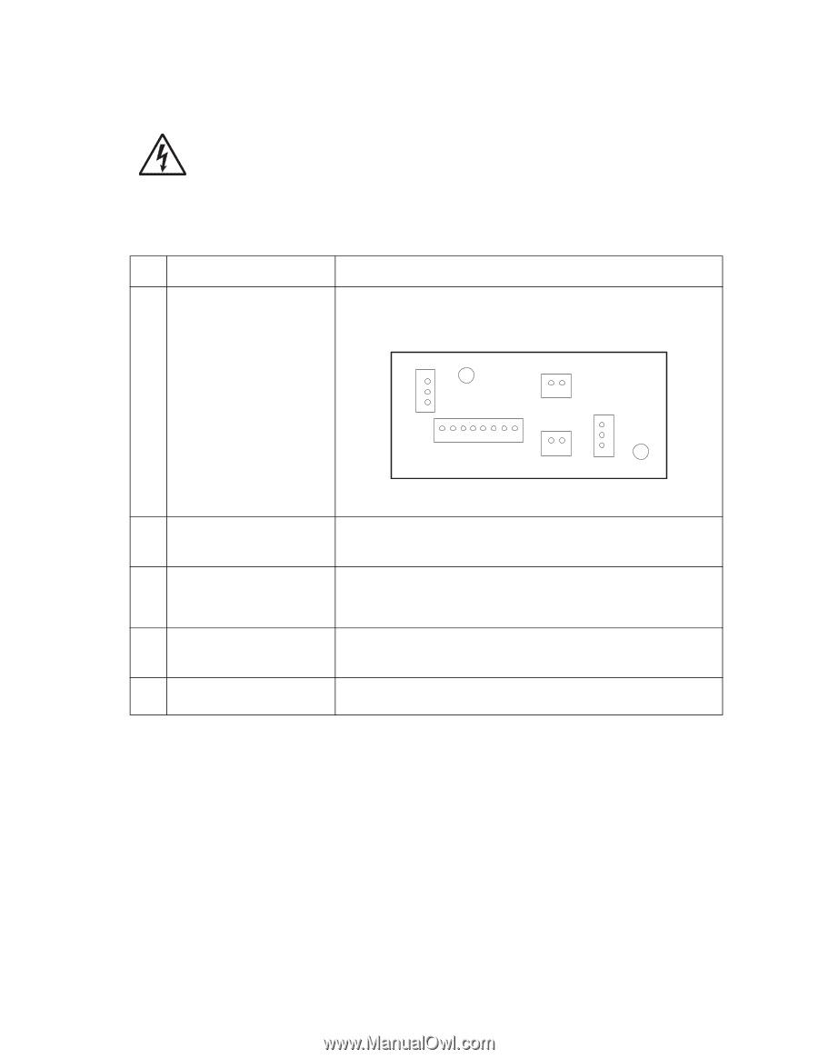
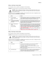
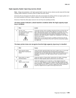
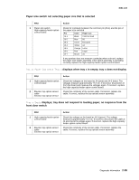
4061-xx0 Fuser solenoid service check CAUTION: There is a danger from hazardous voltage in the area of the printer where you are working. Unplug the printer before you begin, or use caution if the printer must receive power in order to perform the task. Service tip: Try changing the envelope enhance level setting. A different setting may correct the problem. Note: Check the fuser envelope conditioner solenoid adjustment as described in the adjustment section "Fuser solenoid adjustment" on page 4-2. FRU 1 Fuser envelope conditioner solenoid Action Observe the operation of the fuser solenoid by removing the redrive assembly. Check for proper mechanical operation of the solenoid and associated hardware, link, and so on. If correct, check the resistance of the solenoid between J4-1 and J4-2 on the fuser control board. 2 System board 3 LVPS 4 Fuser board to system board cable 5 Fuser assembly 1 J2 1 J1 1 J4 1 J5 1 J6 The resistance measures between 5 ohms and 10 ohms. If incorrect, replace the fuser assembly. If correct, go to step 2. Measure the voltage at the +50 V dc test point on the system board. The voltage should measure approximately +50 V dc. If incorrect, go to step 3. If incorrect, go to step 4. Measure the voltage at CN2-18 on the LVPS. The voltage should measure approximately +50 V dc. If incorrect, replace the LVPS assembly. If correct, replace the system board. If this does not fix the problem, replace the interconnect card assembly. Make sure the cable is connected properly to the system board and fuser control board. Reconnect the cable, if necessary. If the cable is connected correctly, go to step 5. If no problems were found in steps 1 through 4, replace the fuser assembly. See "Fuser assembly removal" on page 4-26. 2-94 Service Manual
-
 1
1 -
2
-
3
-
4
-
5
-
6
-
7
-
8
-
9
-
10
-
11
-
12
-
13
-
14
-
15
-
16
-
17
-
18
-
19
-
20
-
21
-
22
-
23
-
24
-
25
-
26
-
27
-
28
-
29
-
30
-
31
-
32
-
33
-
34
-
35
-
36
-
37
-
38
-
39
-
40
-
41
-
42
-
43
-
44
-
45
-
46
-
47
-
48
-
49
-
50
-
51
-
52
-
53
-
54
-
55
-
56
-
57
-
58
-
59
-
60
-
61
-
62
-
63
-
64
-
65
-
66
-
67
-
68
-
69
-
70
-
71
-
72
-
73
-
74
-
75
-
76
-
77
-
78
-
79
-
80
-
81
-
82
-
83
-
84
-
85
-
86
-
87
-
88
-
89
-
90
-
91
-
92
-
93
-
94
-
95
-
96
-
97
-
98
-
99
-
100
-
101
-
102
-
103
-
104
-
105
-
106
-
107
-
108
-
109
-
110
-
111
-
112
-
113
-
114
-
115
-
116
-
117
-
118
-
119
-
120
-
121
-
122
-
123
-
124
-
125
-
126
-
127
-
128
-
 129
129 -
 130
130 -
 131
131 -
 132
132 -
 133
133 -
 134
134 -
 135
135 -
 136
136 -
 137
137 -
 138
138 -
 139
139 -
140
-
141
-
142
-
143
-
144
-
145
-
146
-
147
-
148
-
149
-
150
-
151
-
152
-
153
-
154
-
155
-
156
-
157
-
158
-
159
-
160
-
161
-
162
-
163
-
164
-
165
-
166
-
167
-
168
-
169
-
170
-
171
-
172
-
173
-
174
-
175
-
176
-
177
-
178
-
179
-
180
-
181
-
182
-
183
-
184
-
185
-
186
-
187
-
188
-
189
-
190
-
191
-
192
-
193
-
194
-
195
-
196
-
197
-
198
-
199
-
200
-
201
-
202
-
203
-
204
-
205
-
206
-
207
-
208
-
209
-
210
-
211
-
212
-
213
-
214
-
215
-
216
-
217
-
218
-
219
-
220
-
221
-
222
-
223
-
224
-
225
-
226
-
227
-
228
-
229
-
230
-
231
-
232
-
233
-
234
-
235
-
236
-
237
-
238
-
239
-
240
-
241
-
242
-
243
-
244
-
245
-
246
-
247
-
248
-
249
-
250
-
251
-
252
-
253
-
254
-
255
-
256
-
257
-
258
-
259
-
260
-
261
-
262
-
263
-
264
-
265
-
266
-
267
-
268
-
269
-
270
-
271
-
272
-
273
-
274
-
275
-
276
-
277
-
278
-
279
-
280
-
281
-
282
-
283
-
284
-
285
-
286
-
287
-
288
-
289
-
290
-
291
-
292
-
293
-
294
-
295
-
296
-
297
-
298
-
299
-
300
-
301
-
302
-
303
-
304
-
305
-
306
-
307
-
308
-
309
-
310
-
311
-
312
-
313
-
314
-
315
-
316
-
317
-
318
-
319
-
320
-
321
-
322
-
323
-
324
-
325
-
326
-
327
-
328
-
329
-
330
-
331
-
332
-
333
-
334
-
335
-
336
-
337
-
338
-
339
-
340
-
341
-
342
-
343
-
344
-
345
-
346
-
347
-
348
-
349
-
350
-
351
-
352
-
353
-
354
-
355
-
356
-
357
-
358
-
359
-
360
-
361
-
362
-
363
-
364
-
365
-
366
-
367
-
368
-
369
-
370
-
371
-
372
-
373
-
374
-
375
-
376
-
377
-
378
-
379
-
380
-
381
-
382
-
383
-
384
-
385
-
386
-
387
-
388
-
389
-
390
-
391
-
392
-
393
-
394
-
395
-
396
-
397
-
398
-
399
-
400
-
401
-
402
-
403
-
404
-
405
-
406
-
407
-
408
-
409
-
410
-
411
-
412
-
413
-
414
-
415
-
416
-
417
-
418
-
419
-
420
-
421
-
422
 |
 |