Lexmark T642 Service Manual - Page 146
Operator panel service check, One or more operator panel buttons fail, No buttons work - parts list
 |
UPC - 734646722001
View all Lexmark T642 manuals
Add to My Manuals
Save this manual to your list of manuals |
Page 146 highlights
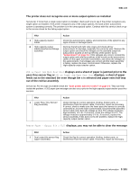
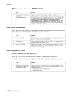
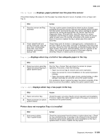
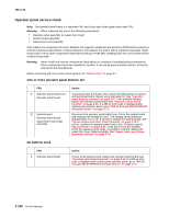
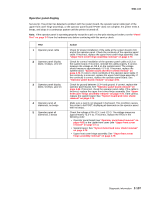
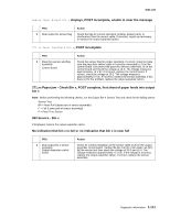
4061-xx0 Operator panel service check Note: The operator panel board is a separate FRU and is also part of the upper front cover FRU Warning: When replacing any one of the following components: • Operator panel assembly (or upper front cover) • System board assembly • Interconnect card assembly Only replace one component at a time. Replace the required component and perform a POR before replacing a second component listed above. If this procedure is not followed, the printer will be rendered inoperable. Never replace two or more of the components listed above without a POR after installing each one or the printer will be rendered inoperable. Warning: Never install and remove components listed above as a method of troubleshooting components. Once a component has been installed in a printer, it can not be used in another printer. It must be returned to the manufacturer. Before continuing with this service check perform the "Button Test" on page 3-7. One or more operator panel buttons fail FRU 1 Operator panel buttons kit Operator panel board 2 System board Operator panel board Upper front cover hinge assembly Action If any button fails the Button Test, check the failing button or buttons and associated parts. Repair using the button kit. See "Operator panel buttons removal" on page 4-67. If the problem remains, replace the operator panel board (see "Operator panel board removal" on page 4-66. If a 950.xx error code is displayed after replacing the operator panel, go to "950.00 through 950.29 EPROM mismatch failure" on page 2-77. Disconnect the operator panel cable from J13 on the system board and measure the voltage at J13-5. The voltage should measure approximately +3.3 V dc. If incorrect, replace the system board. See "System board and inner shield removal" on page 4-76. If correct, replace the operator panel board. See "Operator panel board removal" on page 4-66. If this does not fix the problem, check the operator panel cable. If a problem is found, replace the upper front cover hinge assembly. See "Upper front cover hinge assembly removal" on page 4-78. No buttons work FRU 1 Operator panel board Action If none of the buttons work, replace the operator panel board (see "Operator panel board removal" on page 4-66. If a 950.xx error code is displayed after replacing the operator panel, go to "950.00 through 950.29 EPROM mismatch failure" on page 2-77. 2-106 Service Manual
-
 1
1 -
2
-
3
-
4
-
5
-
6
-
7
-
8
-
9
-
10
-
11
-
12
-
13
-
14
-
15
-
16
-
17
-
18
-
19
-
20
-
21
-
22
-
23
-
24
-
25
-
26
-
27
-
28
-
29
-
30
-
31
-
32
-
33
-
34
-
35
-
36
-
37
-
38
-
39
-
40
-
41
-
42
-
43
-
44
-
45
-
46
-
47
-
48
-
49
-
50
-
51
-
52
-
53
-
54
-
55
-
56
-
57
-
58
-
59
-
60
-
61
-
62
-
63
-
64
-
65
-
66
-
67
-
68
-
69
-
70
-
71
-
72
-
73
-
74
-
75
-
76
-
77
-
78
-
79
-
80
-
81
-
82
-
83
-
84
-
85
-
86
-
87
-
88
-
89
-
90
-
91
-
92
-
93
-
94
-
95
-
96
-
97
-
98
-
99
-
100
-
101
-
102
-
103
-
104
-
105
-
106
-
107
-
108
-
109
-
110
-
111
-
112
-
113
-
114
-
115
-
116
-
117
-
118
-
119
-
120
-
121
-
122
-
123
-
124
-
125
-
126
-
127
-
128
-
129
-
130
-
131
-
132
-
133
-
134
-
135
-
136
-
137
-
138
-
139
-
140
-
 141
141 -
 142
142 -
 143
143 -
 144
144 -
 145
145 -
 146
146 -
 147
147 -
 148
148 -
 149
149 -
 150
150 -
 151
151 -
152
-
153
-
154
-
155
-
156
-
157
-
158
-
159
-
160
-
161
-
162
-
163
-
164
-
165
-
166
-
167
-
168
-
169
-
170
-
171
-
172
-
173
-
174
-
175
-
176
-
177
-
178
-
179
-
180
-
181
-
182
-
183
-
184
-
185
-
186
-
187
-
188
-
189
-
190
-
191
-
192
-
193
-
194
-
195
-
196
-
197
-
198
-
199
-
200
-
201
-
202
-
203
-
204
-
205
-
206
-
207
-
208
-
209
-
210
-
211
-
212
-
213
-
214
-
215
-
216
-
217
-
218
-
219
-
220
-
221
-
222
-
223
-
224
-
225
-
226
-
227
-
228
-
229
-
230
-
231
-
232
-
233
-
234
-
235
-
236
-
237
-
238
-
239
-
240
-
241
-
242
-
243
-
244
-
245
-
246
-
247
-
248
-
249
-
250
-
251
-
252
-
253
-
254
-
255
-
256
-
257
-
258
-
259
-
260
-
261
-
262
-
263
-
264
-
265
-
266
-
267
-
268
-
269
-
270
-
271
-
272
-
273
-
274
-
275
-
276
-
277
-
278
-
279
-
280
-
281
-
282
-
283
-
284
-
285
-
286
-
287
-
288
-
289
-
290
-
291
-
292
-
293
-
294
-
295
-
296
-
297
-
298
-
299
-
300
-
301
-
302
-
303
-
304
-
305
-
306
-
307
-
308
-
309
-
310
-
311
-
312
-
313
-
314
-
315
-
316
-
317
-
318
-
319
-
320
-
321
-
322
-
323
-
324
-
325
-
326
-
327
-
328
-
329
-
330
-
331
-
332
-
333
-
334
-
335
-
336
-
337
-
338
-
339
-
340
-
341
-
342
-
343
-
344
-
345
-
346
-
347
-
348
-
349
-
350
-
351
-
352
-
353
-
354
-
355
-
356
-
357
-
358
-
359
-
360
-
361
-
362
-
363
-
364
-
365
-
366
-
367
-
368
-
369
-
370
-
371
-
372
-
373
-
374
-
375
-
376
-
377
-
378
-
379
-
380
-
381
-
382
-
383
-
384
-
385
-
386
-
387
-
388
-
389
-
390
-
391
-
392
-
393
-
394
-
395
-
396
-
397
-
398
-
399
-
400
-
401
-
402
-
403
-
404
-
405
-
406
-
407
-
408
-
409
-
410
-
411
-
412
-
413
-
414
-
415
-
416
-
417
-
418
-
419
-
420
-
421
-
422
 |
 |