Panasonic HPX300 Operating Instructions - Page 65
Viewfinder Screen Status Displays, Viewfinder Status Indication Layout
 |
UPC - 791871304297
View all Panasonic HPX300 manuals
Add to My Manuals
Save this manual to your list of manuals |
Page 65 highlights
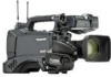
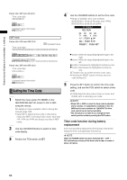
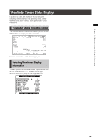
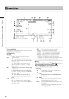
Chapter 4 Adjustments and Settings for Recording Viewfinder Screen Status Displays In addition to video, the viewfinder shows messages indicating camera settings and operating status, center markers, safety zone markers, zebra patterns and other indications. Viewfinder Status Indication Layout The illustration below shows the indications (except MODE CHECK) that are displayed in the viewfinder. TC 1 2 : 3 4 : 5 6 : 2 3 12 P2 LACK I - PAUSE 1394 1080 i AVC-I100 1 9 9 9 min B 9 0% USER - 1 CAC FBC PROXY L T . BOX 6 0 : 2 4PN = = = C H 1 C H 2 ===== 8 3% ND1 FEB 2 5 DRS 1/ 2 5 0 2008 SPOT F5 . 6 P 3 .2 K 0 dB ND 1 23 : 59 : 59 Z99 For more information, see the following pages: Selecting Viewfinder Display Information To select items in the viewfinder screen, open the DISPLAY SETUP screen and turn on or off each item or type. Refer to the section [Using the menus] (page 120). DISPLAY SETUP EVF PEAK LEVEL EVF PEAK FREQ EVF SETTING EVF B. LIGHT EVF COLOR ZEBRA1 DETECT ZEBRA2 DETECT ZEBRA2 0 LOW >>> NORMAL ON 70% 85% SPOT PUSH MENU TO RETURN 65
-
 1
1 -
2
-
3
-
4
-
5
-
6
-
7
-
8
-
9
-
10
-
11
-
12
-
13
-
14
-
15
-
16
-
17
-
18
-
19
-
20
-
21
-
22
-
23
-
24
-
25
-
26
-
27
-
28
-
29
-
30
-
31
-
32
-
33
-
34
-
35
-
36
-
37
-
38
-
39
-
40
-
41
-
42
-
43
-
44
-
45
-
46
-
47
-
48
-
49
-
50
-
51
-
52
-
53
-
54
-
55
-
56
-
57
-
58
-
59
-
 60
60 -
 61
61 -
 62
62 -
 63
63 -
 64
64 -
 65
65 -
 66
66 -
 67
67 -
 68
68 -
 69
69 -
 70
70 -
71
-
72
-
73
-
74
-
75
-
76
-
77
-
78
-
79
-
80
-
81
-
82
-
83
-
84
-
85
-
86
-
87
-
88
-
89
-
90
-
91
-
92
-
93
-
94
-
95
-
96
-
97
-
98
-
99
-
100
-
101
-
102
-
103
-
104
-
105
-
106
-
107
-
108
-
109
-
110
-
111
-
112
-
113
-
114
-
115
-
116
-
117
-
118
-
119
-
120
-
121
-
122
-
123
-
124
-
125
-
126
-
127
-
128
-
129
-
130
-
131
-
132
-
133
-
134
-
135
-
136
-
137
-
138
-
139
-
140
-
141
-
142
-
143
-
144
-
145
-
146
-
147
-
148
-
149
-
150
-
151
-
152
-
153
-
154
-
155
-
156
-
157
-
158
-
159
-
160
-
161
-
162
-
163
-
164
-
165
-
166
 |
 |