Panasonic WVCU650 Operating Instructions
Panasonic WVCU650 - SYSTEM CONTROLLER ADDENDUM Manual
 |
UPC - 791871504277
View all Panasonic WVCU650 manuals
Add to My Manuals
Save this manual to your list of manuals |
Panasonic WVCU650 manual content summary:
- Panasonic WVCU650 | Operating Instructions - Page 1
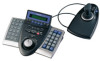
Operating Instructions System Controller WV-CU650 Model No. Before attempting to connect or operate this product, please read these instructions carefully and save this manual for future use. - Panasonic WVCU650 | Operating Instructions - Page 2
of electric shock to persons. The exclamation point within an equilateral triangle is intended to alert the user to the presence of important operating and maintenance (servicing) instructions in the literature accompanying the appliance. For U.S.A NOTE: This equipment has been tested and found to - Panasonic WVCU650 | Operating Instructions - Page 3
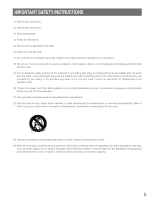
manufacturer's instructions. 8) service personnel. Servicing is required when the apparatus has been damaged in any way, such as power-supply cord or plug is damaged, liquid has been spilled or objects fallen into the apparatus, the apparatus has been exposed to rain or moisture, does not operate - Panasonic WVCU650 | Operating Instructions - Page 4
the 3D Joystick Unit 17 ■ Adjustment of 3D Joystick 17 SETUP PROCEDURES (HARDWARE 18 ■ Setup Procedures 18 ■ MODE Switch Setting 18 ■ CONTROLLER NO. Switch Setting 18 SETUP PROCEDURES (FIRMWARE 19 ■ Administrator Password Entry 19 ■ Setting Modes 19 ■ All Reset 20 ■ PS·Data Communication - Panasonic WVCU650 | Operating Instructions - Page 5
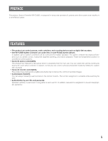
WV-CU650, is designed for setup and operation of cameras and other system units installed in a surveillance system. FEATURES • This product can control cameras, matrix switchers, and recording devices such as digital disk recorders. • One WV-CU650 System Controller can control two or more PS·Data - Panasonic WVCU650 | Operating Instructions - Page 6
operate PS·Data system units and connected cameras. (A surveillance control system cannot be composed of this product alone.) IN NO EVENT SHALL MATSUSHITA ELECTRIC INDUSTRIAL CO., LTD. BE LIABLE TO ANY PARTY OR ANY PERSON, EXCEPT FOR CERTAIN WARRANTY PROGRAM OFFERED BY THE LOCAL DEALER OF PANASONIC - Panasonic WVCU650 | Operating Instructions - Page 7
describing the use and operation of this unit. System controller: Panasonic System Controller WV-CU650 Caution(s): Caution statements identify conditions or practices that could result in damage to this product or injury. Note(s): Note statements identify special instruction, rule, or side comment - Panasonic WVCU650 | Operating Instructions - Page 8
i u !0 y WV-CU650 ALARM ACK ALM RESET ALM SUSPEND OSD ALM ALL RESET ALM RECALL CAM FUNC SEQ PAUSE SYS FUNC TOUR SEQ MON LOCK SEQ STOP GROUP SEQ MULTI SCREEN EL-ZOOM LOGOUT GO TO LAST AUX1 ON AUX2 ON MARK ADJUST MENU F1 F2 F3 F4 EXIT ENTER SYSTEM CONTROLLER SHIFT ALM OPERATE ALARM - Panasonic WVCU650 | Operating Instructions - Page 9
camera by the function number. • When you press while holding down the SHIFT button, this button recalls a function of external system unit by . You can start playback at the start point. (Refer to the operating instructions of recorder.) Note: This button is available only for Digital Disk Recorder - Panasonic WVCU650 | Operating Instructions - Page 10
operation differs from "Hold playback speed" performed by holding the shuttle ring of recorder. When you hold the playback speed from the system controller Displays the numbers of unit, monitor and camera currently selected. The (F1 to F4/F5 to F8) or joystick function buttons (A, B, and top buttons). - Panasonic WVCU650 | Operating Instructions - Page 11
a PC for system configuration. $6 Data ports (DATA) These ports are used for connection with the system controller and other system units. These ports are also used when adding other system controller connections. $7 Mode Selection switches (MODE) The operation mode of system controller is selected - Panasonic WVCU650 | Operating Instructions - Page 12
■ 3D Joystick Unit This joystick unit is used to operate combination cameras and pan/tilt heads manually. %2 OPEN IRIS FAR FOCUS %3 A CLOSE NEAR B %4 %1 %5 %0 %0 Top button The top button is pressed to recall a function already assigned. %1 Zoom wheel controller This controller is used - Panasonic WVCU650 | Operating Instructions - Page 13
Note: Some parts of LCD camera posi- tion number is displayed. • When a sequence is activated for a connected system unit, "Seq" is displayed. e Model number/Unit number • The model number of connected system unit is dis- played. When you select a system unit, the unit number of connected system unit - Panasonic WVCU650 | Operating Instructions - Page 14
is displayed. Note: Refer to p. 48 Menu Function Categories. ● Sub Menu (Menu Functions) e Function name The name of selected menu function is displayed. Camera Setup 101 On Off Rst A.Rst F1 F2 F3 F4 q Menu name The name of selected menu function is displayed. w Function number The function - Panasonic WVCU650 | Operating Instructions - Page 15
which a camera number other than 1 to 256 has been entered. • In this document, gray area on illustration shows blinking. Controller No.1 No Exist Error Controller No.1 No Exist Error This message is displayed when no system controller is set to CONTROLLER NO.1. Check that a system controller is set - Panasonic WVCU650 | Operating Instructions - Page 16
WJ-HD300 Series To PS·Data ports Used when adding other WV-CU650 system controllers (Available up to 3) Modular cable (supplied) System Controller WV-CU650 (Main unit) 16 456 456 JOYSTICK SERIAL DATA 901 MODE CONTROLLER NO. DC9V IN Fixed Line termination: ON PS·Data Mode OFF ON MODE - Panasonic WVCU650 | Operating Instructions - Page 17
■ Connection with the 3D Joystick Unit Connect the main unit and 3D joystick unit as follows. Main unit JOYSTICK SERIAL DATA 901 MODE CONTROLLER NO. 78 456 23 DC9V IN Combination code label has been stuck on the bottom. Cable (supplied) 3D joystick unit Bottom side DOWN UP Cable - Panasonic WVCU650 | Operating Instructions - Page 18
two or more system controllers in daisy chain connections. (Refer to CONTROLLER NO. Setting.) 3. Perform WV-CU650 setups after entering the administrator password. You will perform the settings concerning password and communication between system controllers and other system units, etc. (Refer to - Panasonic WVCU650 | Operating Instructions - Page 19
can be changed. MON (ESC) and 2 PS·Data database copy The PS·Data database can be copied from the source system controller (Controller No. 1) to a destination system controller. MON (ESC) and 4 PS·Data password display The passwords of up to 16 operators can be displayed on the LCD. * The - Panasonic WVCU650 | Operating Instructions - Page 20
password • PS·Data communication setting • LCD brightness, contrast, alarm buzzer, and button buzzer settings • Button functions and joystick button functions (F1 to F8, A, B, and top buttons) • Controller functions (Time & Date Type) (Auto Login) (Operator Setup) (Function Level) (Camera - Panasonic WVCU650 | Operating Instructions - Page 21
the password. • You can change the setting item display on the LCD by rotating the JogDial. 5. Select an item you wish to set up by rotating the JogDial. Baud rate PS • Data Com. Setup Baud Rate 9600 The speed of communication between the system controller and other system units Parity bit PS • Data - Panasonic WVCU650 | Operating Instructions - Page 22
4. Press the MON (ESC) button. The selected parameter will be determined, and the LCD display will return from the editing mode to the display mode. PS • Data Com. Setup Parity Bit Even ● Stop Bit Setting 1. Select "Stop Bit" by rotating the JogDial. (Refer to Step 5 in p. 21.) 2. Press the CAM (SET - Panasonic WVCU650 | Operating Instructions - Page 23
● Group Address Setting for System Controller Note: Remain the factory default. When you have will jump to the sub parameter. PS • Data Com. Setup Sys G-Adr.A 05 5. Enter the unit number of system unit by rotating the JogDial or pressing the + or - button. PS • Data Com. Setup Sys G-Adr.A 01 - Panasonic WVCU650 | Operating Instructions - Page 24
10. Press the CAM (SET) button. The new password has been memorized in the system, and "Memory" will appear on the LCD. Admin Password Setup Memory Then, "End" will appear on the LCD. Admin Password Setup End Note: If the new password entered is wrong, the LCD display will return to Step 4. Enter - Panasonic WVCU650 | Operating Instructions - Page 25
Login) (Operator Setup) (Function Level) (Camera Level) (Cam Posi Map) (Cam-Unit Map) (HDD-Unit Map) (LCD Title) Notes: • Database copy to two or more system controllers is available at a time. • To activate this mode, you need to perform the PS·Data communication settings. (Refer to p. 20 PS·Data - Panasonic WVCU650 | Operating Instructions - Page 26
of source and destination system controllers. ■ PS·Data Operator Password Check In case operators have forgotten their passwords, the administrator can check the passwords in the following procedure. ● Operation 1. Turn off the power. 2. Turn on the power of system controller while holding down - Panasonic WVCU650 | Operating Instructions - Page 27
turned on. Then, the OPERATE indicator will light up. and the software version → controller number → login standby display will appear on the LCD. Power is turned on. Ver.1.00 Software version appears. (Lighting for 2.0 seconds) PS·Data Mode CU Unit No.1 Controller number appears. (Lighting for - Panasonic WVCU650 | Operating Instructions - Page 28
■ Basic Operation Flow System Operation Alarm suspension or reset Login System Unit Selection Monitor Selection System Unit Setup and Operation Camera Selection Camera setup and control Logout Login Unit selection Monitor selection Camera selection Operation (Multiscreen segment switching - Panasonic WVCU650 | Operating Instructions - Page 29
Operator No. User ID 1 650 2 1 3 100 4 101 5 102 6 103 Password 650 12345 100 101 102 103 Function level Camera level 1 1 1 1 2 1 3 1 3 1 3 1 1. Turn on the power. (Refer to p. 27 Power-on and Poweroff.) 2. Wait until the login standby display appears. PS·Data Mode No User - Panasonic WVCU650 | Operating Instructions - Page 30
to ON, operators can log into the system without entering their passwords. The LCD display after power-on becomes as follows. (Refer to p. 61 for details on the setting.) 1. When the power is turned on, "Auto Login" appears on the LCD for a second. PS • Data Mode Auto Login 2. The user ID of auto - Panasonic WVCU650 | Operating Instructions - Page 31
SELECTION To control the system, you need to select a desired unit (system unit, recorder, monitor, or camera) at the beginning. ■ System Unit Selection Notes: • In advance, you need to set the unit number for each system unit. (Refer to the operating instructions of system units.) • 1 to 99 are - Panasonic WVCU650 | Operating Instructions - Page 32
system unit does not support monitor selection. 1. Select a system unit (including a recorder) connected to a monitor you wish to control. (Refer to p. 31 System Unit • Refer to the operating instructions of system unit for available camera numbers. • You can also select cameras by pressing the + or - Panasonic WVCU650 | Operating Instructions - Page 33
Press the EL-ZOOM button. The camera image on the monitor will be zoomed. Every pressing the EL-ZOOM button can change the zooming rate. 3. To move the zoomed area, move the 3D joystick to desired directions. (Refer to the operating instructions of system unit.) Note: Available zooming rates differ - Panasonic WVCU650 | Operating Instructions - Page 34
differs depending on system units. Refer to the operating instructions of system units. ■ System Function Control You can recall system functions (functions of system units) by pressing the corresponding function numbers. Refer to the operating instructions of system units for the association - Panasonic WVCU650 | Operating Instructions - Page 35
RECORDER CONTROL From this system controller, you can control digital disk recorders supporting PS·Data. You will control a recorder in the status in which a recorder has been selected. ■ Manual Recording 1. To start the recording, press the REC button. Recording will be started. Multiscreen - Panasonic WVCU650 | Operating Instructions - Page 36
the monitor display activated by the function buttons, press the MON (ESC) button. • The DATA COPY window is not displayed while a thumbnail window is displayed. • Refer to the operating instructions of recorder for details on each function. Example of searching filter display and settings 1. Repeat - Panasonic WVCU650 | Operating Instructions - Page 37
camera channels, repeat Step 5. 6. Press the CAM (SET) button of main unit or top button of 3D joystick unit. The associated recording event will be displayed on the monitor. ● Operation to the operating instructions of joystick controller to the right or left. • Rotate the - Panasonic WVCU650 | Operating Instructions - Page 38
for controlling the recorder. • Image to be played back differs depending on recorders. (Refer to the operating instructions of to be edited by performing either of the following. • Move the 3D joystick controller to the right or left. • Rotate the shuttle ring clockwise or counterclockwise. - Panasonic WVCU650 | Operating Instructions - Page 39
back differ depending on recorders. (Refer to the operating instructions of recorder.) ■ Other Available Functions Depending on recorders 57 and 72) • Filtering ON/OFF (WJ-HD300 Series only) (p. 58) • Displaying camera and playback image (WJ-HD500 Series only) (p. 58) • Recorded-image copy (WJ-HD500 - Panasonic WVCU650 | Operating Instructions - Page 40
/tilting heads or combination cameras are connected to system units. 1. Select a system unit, monitor, and desired camera. (Refer to p. 31 System Unit Selection, p. 32 Monitor Selection, and p. 32 Camera Selection.) 2. Move the 3D joystick to desired directions. The selected camera will pan and tilt - Panasonic WVCU650 | Operating Instructions - Page 41
Move the camera to a desired position by moving the 3D joystick. 2. Camera Function Control You can recall the camera functions of combination cameras by entering the function number from this system controller. Refer to the operating instructions of combination camera for the association of camera - Panasonic WVCU650 | Operating Instructions - Page 42
select a camera or camera position, this system controller memorizes up to 10 steps of camera selection. You can recall these operations in order or reverse order. In the following procedure, you can track back the camera images formerly displayed. Note: After power-off or system unit selection, the - Panasonic WVCU650 | Operating Instructions - Page 43
71) • Iris reset (p. 71) • Camera +1 (p. 71) • Camera -1 (p. 72) ● Operating Procedure (Latch mode) 1. Select a system unit, monitor, and camera an auxiliary control device is connected to. (Refer to p. 31 System Unit Selection, p. 32 Monitor Selection, and p. 32 Camera Selection.) 2. Press the AUX - Panasonic WVCU650 | Operating Instructions - Page 44
indicator will go out. Notes: • Alarm behaviors differ depending on connected system units. Refer to the operating instructions of system units. • You cannot cancel the alarm mode or alarm auto reset mode of each system unit one by one. ■ Alarm Suspension You can temporarily stop alarm inputs to - Panasonic WVCU650 | Operating Instructions - Page 45
Joystick unit> 3D joystick upward (▲): Moves the cursor up. 3D joystick downward (▼): Moves the cursor down. 3D joystick to the left (t): Moves the cursor to the left. 3D joystick to the right (s): Moves the cursor to the right. Zoom wheel controller Refer to the operating instructions of recorder - Panasonic WVCU650 | Operating Instructions - Page 46
HD200 Ver. 1.24 later or WJ-HD220 supports alarm history search. (Refer to the operating instructions of recorder.) Available buttons and functions F1 edited by perform- ing either of the following. • Move the 3D joystick controller to the right or left. • Rotate the shuttle ring clockwise or - Panasonic WVCU650 | Operating Instructions - Page 47
can assign frequently-used menu functions (system functions and camera functions, etc.) to the F1 to F8 button of system controller. (=Button function) In addition, you can also assign the menu functions to the A, B and top buttons of 3D joystick unit. (=Joystick button function) Only by pressing an - Panasonic WVCU650 | Operating Instructions - Page 48
operation. ● Camera Functions (CAM) Camera Setup LCD MENU CAM 101 Camera Setup • This function displays or closes the camera setup menu for system settings. • You will change camera modes: MANUAL ON, MANUAL OFF, AUTO 1, and AUTO 2. Note: Refer to the operating instructions of camera for details - Panasonic WVCU650 | Operating Instructions - Page 49
You will open the setup menu of system unit and change the settings. SX150 OSD operators. Camera Level LCD MENU CNT 406 Camera Level You will change the camera control levels of operators. Cam Posi Map LCD MENU CNT 407 Cam Posi Map You will register camera positions (the association of camera - Panasonic WVCU650 | Operating Instructions - Page 50
unit numbers). LCD Title LCD MENU LCD Title CNT 410 You will edit the function names of F1 to F8, which are displayed on the LCD. ● Joystick Button Functions (J/S MENU) Camera Function J/S MENU 501 Camera Function A camera function will be activated. System Function J/S MENU 502 System - Panasonic WVCU650 | Operating Instructions - Page 51
units. Refer to the operating instructions of system units. ■ To Recall Menu Functions You can recall menu functions as follows. 1. Select a system unit for which you wish to recall a function. (Refer to p. 31 System Unit Selection, p. 31 Recorder Selection, p. 32 Monitor Selection, or p. 32 Camera - Panasonic WVCU650 | Operating Instructions - Page 52
appear on the LCD. System Setup 301 On Off 5. Perform the operations to activate the selected function. The operating procedure differs depending on each Buttons, or p. 53 To Assign Menu Functions to Joystick Function Buttons. F1: Camera Setup Camera Setup F1 On Off Rst A.Rst F2: Auto Mode - Panasonic WVCU650 | Operating Instructions - Page 53
Camera Function Number 1 is pressed. • Refer to the operating instruction of camera for details on camera function. • Refer to the operating instruction of system unit for details on system Functions and Joystick Button Functions You can recall the assigned button functions and joystick button - Panasonic WVCU650 | Operating Instructions - Page 54
to the F1 button. 2. To check other (joystick) button functions, rotate the JogDial. The button functions and joystick button function will appear on the LCD in the following order. Function Check F1 Camera Setup 101 • • Function Check System Setup F8 301 Function Check A Cam Func "4096 - Panasonic WVCU650 | Operating Instructions - Page 55
or tilt the selected camera by moving the 3D joystick. ● BW Mode You can change the color mode of camera images from color to black and white. This function is activated to improve the camera sensitivity when monitoring a dark place. Note: Refer to the operating instructions of camera for details on - Panasonic WVCU650 | Operating Instructions - Page 56
patrol learn setup will start. 3. Perform desired camera operations by moving the 3D joystick or zoom wheel controller, etc. The following controls are available for patrol learn. • Panning/Tilting (3D joystick) • Iris control (IRIS OPEN/CLOSE buttons) • Focus control (FOCUS FAR/NEAR buttons) • Zoom - Panasonic WVCU650 | Operating Instructions - Page 57
the auto pan direction will be reversed. • Auto pan will be canceled when you pan or tilt the selected camera by moving the 3D joystick. ■ Recorder Functions menu will appear on the LCD. Then, perform the search playback operation. (Refer to p. 35 Search Playback.) Search Mode HD300 Thumb Text - Panasonic WVCU650 | Operating Instructions - Page 58
picture will be displayed on the multiscreen monitor. • The specified camera channel will blink on the LCD for a few seconds, and system units. Refer to the operating instructions of system unit. 1. Display "System Setup" sub menu. (Refer to Step 1 to 4 of p. 51 To Recall Menu Functions.) System - Panasonic WVCU650 | Operating Instructions - Page 59
entry such as a password. Button 0 (WJ- controller to the left: Moves to the previ- ous page. Top button: Determines the selected parameter and moves to the sub menu. 4. Press the F2 button. The setup menu of selected system unit will be closed, and "s" mark will light up beside "Off". ● VCR/Camera - Panasonic WVCU650 | Operating Instructions - Page 60
■ Controller Functions ● Camera Cleaning 1. Display "Camera Cleaning" sub menu. (Refer to Step 1 to 4 of p. 51 To Recall Menu Functions.) Camera Cleaning 401 or move the 3D joystick to the left. 5. Press the F1 button. Camera cleaning will be cleared from the first to the last camera you have set. - Panasonic WVCU650 | Operating Instructions - Page 61
, operators can log into or log out of the system automatically. Note: You cannot set both Auto Login and Auto Logout to ON for the same system controller. shuttle ring clockwise or move the 3D joystick to the right. 4. To activate auto login, select an operator (Operator 1 to 16) by performing the - Panasonic WVCU650 | Operating Instructions - Page 62
will return to Step 1. Auto Login/out 403 Cont No.6 Erased ● Operator Registration or Change You can register new operators or change the parameter settings. Up to 16 operators are registrable in the system. Notes: • Refer to p. 29 Operation Start (Login) for the factory default. • To return to the - Panasonic WVCU650 | Operating Instructions - Page 63
deleted, "No Assign" will appear beside the operator number. Operator Setup 404 Operator07 No Assign ● Function Level Setting You can change the function levels for each button (except for numeric buttons) of main unit and 3D joystick unit. The function levels range between Table No. 1 (highest - Panasonic WVCU650 | Operating Instructions - Page 64
E E 05 TOP SW E E 06 JOYSTICK E E 07 FOCUS NEAR/FAR E E 08 IRIS OPEN/CLOSE E D 09 CAM/SET E E 10 MON/ESC E E 11 UNIT E E 12 RECORDER E E 13 CAM return to Step 1. ● Camera Level Setting You can change the camera levels for each operator. The camera levels range between Table No - Panasonic WVCU650 | Operating Instructions - Page 65
joystick to the left. 6. Select E (= Enabled) or D (= Disabled) by performing either of the following. • Rotate the JogDial clockwise or counterclockwise. • Press the + or - button. Camera Table3 406 Cam064 =D E (= Enabled): The operator can display the camera image on the monitor and control - Panasonic WVCU650 | Operating Instructions - Page 66
66 ● Associating Camera Numbers with Unit Numbers You can register camera-unit maps (the association of camera numbers and unit numbers). Up to 256 camera unit maps can be registered. You can select a camera by entering the camera channel alone, even if the camera is connected to system unit not - Panasonic WVCU650 | Operating Instructions - Page 67
or CAM (SET) button again. The specified camera channel and unit number will be set for the selected camera-unit map. "Memory" will appear on the LCD for the shuttle ring counterclockwise or move the 3D joystick to the left. 4. Select a desired unit number by performing either of the following. • - Panasonic WVCU650 | Operating Instructions - Page 68
camera channel area. "HDD-Unit Map Check" menu will appear on the LCD. ● LCD Title Editing You can edit button function titles displayed on the LCD. If you set LCD titles related to the registered button functions, controllability or counterclockwise) or move the 3D joystick (to the right or left) • - Panasonic WVCU650 | Operating Instructions - Page 69
will become as follows. Camera Function A Code=0007 ● System Function You can recall system functions by entering function numbers from this system controller. Note: Refer to the operating instruction of system unit for details on system function. 1. Display "Camera Function" sub menu. (Refer - Panasonic WVCU650 | Operating Instructions - Page 70
504 "Enter F1 Button" F1 F2 F3 F4 ● Patrol Play You can activate the patrol play function for the selected camera. Note: Refer to the operating instruction of camera for details of this function. 1. Display "Patrol Play" sub menu. (Refer to Step 1 to 4 of p. 51 To Recall Menu Functions - Panasonic WVCU650 | Operating Instructions - Page 71
, the LCD display will become as follows. Home Position A ● Auto Focus You can activate the auto focus function for the selected camera. Note: Refer to the operating instruction of camera for details of this function. 1. Display "Auto Focus" sub menu. (Refer to Step 1 to 4 of p. 51 To Recall Menu - Panasonic WVCU650 | Operating Instructions - Page 72
camera channel will be displayed on the active monitor. Note: When the Camera -1 function has been activated with the A button, the LCD display will become as follows. Camera an external recording device. Note: Refer to the operating instruction of recorder for details of this function. 1. Display - Panasonic WVCU650 | Operating Instructions - Page 73
start point to the next alarm record of recorded image data. Note: Refer to the operating instruction of recorder for details of this function. 1. Display " system unit. Note: Available multiscreen segment patterns differ depending on system units. Refer to the operating instructions of system units - Panasonic WVCU650 | Operating Instructions - Page 74
may not be authorized to control cameras with the 3D joystick. Check the user level settings of these users. Refer to pp. 62 to 65. Users cannot log into the system. Cables may be disconnected from either the DATA ports of system controller or other system units. Check the connections. Refer to - Panasonic WVCU650 | Operating Instructions - Page 75
to the operating instructions of selected system unit. Users who have logged into the system may not be authorized to control cameras with the button. Check the user level settings of these users. Refer to pp. 62 to 65. Operation is suddenly discontinued while controlling system units. "ALM - Panasonic WVCU650 | Operating Instructions - Page 76
● System Controller Power Source: Power Source (Supplied AC Adapter): Data Output/Input Port: Serial port: Controller Number: Ambient Operating Temperature: Unit Number Selection: Monitor Number Selection: Camera Number Selection: Dimensions Main Unit: 3D joystick Unit: Weight Main Unit: 3D joystick - Panasonic WVCU650 | Operating Instructions - Page 77
77 - Panasonic WVCU650 | Operating Instructions - Page 78
Digital Communications & Security Company Unit of Matsushita Electric Corporation of America Security Systems Group www.panasonic.com/cctv Executive Office: One Panasonic Way 3E-7, Secaucus, New Jersey 07094 Zone Office Eastern: One Panasonic Way, Secaucus, NJ 07094 (201) 348-7303 Central: 1707
-
 1
1 -
 2
2 -
 3
3 -
 4
4 -
 5
5 -
 6
6 -
 7
7 -
8
-
9
-
10
-
11
-
12
-
13
-
14
-
15
-
16
-
17
-
18
-
19
-
20
-
21
-
22
-
23
-
24
-
25
-
26
-
27
-
28
-
29
-
30
-
31
-
32
-
33
-
34
-
35
-
36
-
37
-
38
-
39
-
40
-
41
-
42
-
43
-
44
-
45
-
46
-
47
-
48
-
49
-
50
-
51
-
52
-
53
-
54
-
55
-
56
-
57
-
58
-
59
-
60
-
61
-
62
-
63
-
64
-
65
-
66
-
67
-
68
-
69
-
70
-
71
-
72
-
73
-
74
-
75
-
76
-
77
-
78
 |
 |
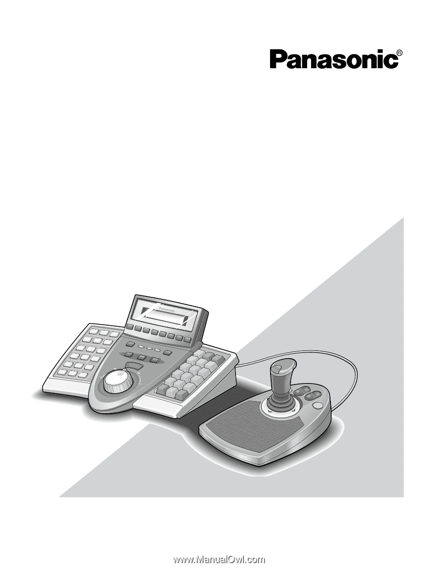
Before attempting to connect or operate this product,
please read these instructions carefully and save this manual for future use.
Model No.
WV-CU650
System Controller
Operating Instructions