Panasonic WVCU650 Operating Instructions - Page 11
Rear View, DC 9V Input jack DC 9V
 |
UPC - 791871504277
View all Panasonic WVCU650 manuals
Add to My Manuals
Save this manual to your list of manuals |
Page 11 highlights
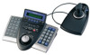
● Rear View JOYSTICK SERIAL DATA MODE CONTROLLER NO. DC9V IN $4 $5 $6 $7 $8 $9 $4 Joystick connector (JOYSTICK) This connector is used for connection with the joystick. $5 Serial port (SERIAL) This port is used for connection with a PC for system configuration. $6 Data ports (DATA) These ports are used for connection with the system controller and other system units. These ports are also used when adding other system controller connections. $7 Mode Selection switches (MODE) The operation mode of system controller is selected with these switches. $8 Controller Number switch (CONTROLLER NO.) When two or more system controllers are connected in the system, this switch determines the unit number of each controller. (Refer to p. 18 for the setting.) If connecting only one system controller in the system, set this switch to "1". $9 DC 9V Input jack (DC 9V IN) An AC adapter, supplied with the system controller, is plugged into this jack. 11
-
 1
1 -
2
-
3
-
4
-
5
-
 6
6 -
 7
7 -
 8
8 -
 9
9 -
 10
10 -
 11
11 -
 12
12 -
 13
13 -
 14
14 -
 15
15 -
 16
16 -
17
-
18
-
19
-
20
-
21
-
22
-
23
-
24
-
25
-
26
-
27
-
28
-
29
-
30
-
31
-
32
-
33
-
34
-
35
-
36
-
37
-
38
-
39
-
40
-
41
-
42
-
43
-
44
-
45
-
46
-
47
-
48
-
49
-
50
-
51
-
52
-
53
-
54
-
55
-
56
-
57
-
58
-
59
-
60
-
61
-
62
-
63
-
64
-
65
-
66
-
67
-
68
-
69
-
70
-
71
-
72
-
73
-
74
-
75
-
76
-
77
-
78
 |
 |
