Yamaha RX V661 MCXSP10 Manual - Page 11
Step 2: Connect your DVD player and other components, INTRODUCTION, English - av receiver
 |
UPC - 027108927411
View all Yamaha RX V661 manuals
Add to My Manuals
Save this manual to your list of manuals |
Page 11 highlights
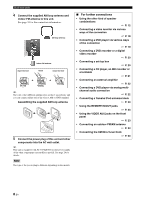
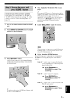
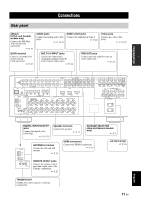
INTRODUCTION Quick start guide Step 2: Connect your DVD player and other components AUDIO L GND R DOCK PHONO XM IN MD/ OUT CD (PLAY) CD-R (REC) DVD DTV/CBL IN OUT DVR MULTI CH INPUT L ZONE 2 CENTER OUT PRE OUT SINGLE CENTER VIDEO VIDEO IN OUT VCR R FRONT(6CH) SB(8CH) SURROUND HDMI SUB WOOFER S VIDEO SUB FRONT SURROUND SUR. BACK WOOFER DVD DTV/CBL IN OUT DVR IN OUT VCR MONITOR OUT COMPONENT VIDEO PR A DVD PB Y PR B DTV/CBL PB Y ANTENNA AM GND MD/CD-R MD/CD-R DVD DTV/CBL CD DVD 1 2 3 4 5 6 DIGITAL OUTPUT OPTICAL COAXIAL DIGITAL INPUT FRONT B/ZONE2/ R EXTRA SP L FRONT A R L FM 75 UNBAL REMOTE TRIGGER OUT DVD IN1 DTV/CBL IN2 OUT SPEAKERS CENTER SURROUND R L SURROUND BACK/BI-AMP R L MONITOR OUT AC OUTLETS C DVR +12V IN OUT 15mA MAX. PRESENCE SINGLE 2 Connect the video cable to the composite video output jack of your DVD player and DVD VIDEO jack of this unit. DVD player AV receiver DVD VIDEO jack Make sure that this unit and the DVD player are unplugged from the AC wall outlets. Composite video output jack Video cable 1 Connect the digital coaxial audio cable to the digital coaxial audio output jack of your DVD player and the DVD COAXIAL jack of this unit. DVD player AV receiver 3 Connect the video cable to the VIDEO MONITOR OUT jack of this unit and the video input jack of your video monitor. Video monitor AV receiver Digital coaxial audio output jack Digital coaxial audio cable Video input jack DVD DIGITAL INPUT coaxial jack Video cable VIDEO MONITOR OUT jack English 7 En
-
 1
1 -
2
-
3
-
4
-
5
-
 6
6 -
 7
7 -
 8
8 -
 9
9 -
 10
10 -
 11
11 -
 12
12 -
 13
13 -
 14
14 -
 15
15 -
 16
16 -
17
-
18
-
19
-
20
-
21
-
22
-
23
-
24
-
25
-
26
-
27
-
28
-
29
-
30
-
31
-
32
-
33
-
34
-
35
-
36
-
37
-
38
-
39
-
40
-
41
-
42
-
43
-
44
-
45
-
46
-
47
-
48
-
49
-
50
-
51
-
52
-
53
-
54
-
55
-
56
-
57
-
58
-
59
-
60
-
61
-
62
-
63
-
64
-
65
-
66
-
67
-
68
-
69
-
70
-
71
-
72
-
73
-
74
-
75
-
76
-
77
-
78
-
79
-
80
-
81
-
82
-
83
-
84
-
85
-
86
-
87
-
88
-
89
-
90
-
91
-
92
-
93
-
94
-
95
-
96
-
97
-
98
-
99
-
100
-
101
-
102
-
103
-
104
-
105
-
106
-
107
-
108
-
109
-
110
-
111
-
112
-
113
-
114
-
115
-
116
-
117
-
118
-
119
-
120
-
121
-
122
-
123
-
124
-
125
-
126
-
127
-
128
-
129
-
130
 |
 |
