Yamaha RX V661 MCXSP10 Manual - Page 19
Information on jacks and cable plugs, Audio jacks - video
 |
UPC - 027108927411
View all Yamaha RX V661 manuals
Add to My Manuals
Save this manual to your list of manuals |
Page 19 highlights
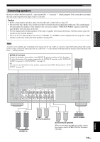
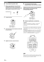
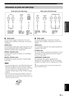
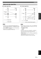
PREPARATION Information on jacks and cable plugs Connections Audio jacks and cable plugs AUDIO L R DIGITAL COAXIAL DIGITAL OPTICAL Video jacks and cable plugs VIDEO S VIDEO COMPONENT VIDEO Y PB PR (White) (Red) (Orange) (Yellow) (Green) (Blue) (Red) L R C O V S Y PB PR Left and right analog audio cable plugs Coaxial digital audio cable plug Optical digital audio cable plug Composite video cable plug S-video cable plug Component video cable plugs ■ Audio jacks This unit has three types of audio jacks. Connection depends on the availability of audio jacks on your other components. AUDIO jacks For conventional analog audio signals transmitted via left and right analog audio cables. Connect red plugs to the right jacks and white plugs to the left jacks. DIGITAL COAXIAL jacks For digital audio signals transmitted via coaxial digital audio cables. DIGITAL OPTICAL jacks For digital audio signals transmitted via optical digital audio cables. Notes • You can use the digital jacks to input PCM, Dolby Digital and DTS bitstreams. When you connect components to both the COAXIAL and OPTICAL jacks, priority is given to the signals input at the COAXIAL jack. All digital input jacks are compatible with digital signals with up to 96 kHz of sampling frequency. • Pull out the cap from the optical jack before you connect the fiber optic cable. Do not discard the cap. When you are not using the optical jack, be sure to put the cap back in place. This cap protects the jack from dust. ■ Video jacks This unit has three types of video jacks. Connection depends on the availability of input jacks on your video monitor. VIDEO jacks For conventional composite video signals transmitted via composite video cables. S VIDEO jacks For S-video signals, separated into the luminance (Y) and chrominance (C) video signals transmitted on separate wires of S-video cables. COMPONENT VIDEO jacks For component video signals, separated into the luminance (Y) and chrominance (PB, PR) video signals transmitted on separate wires of component video cables. y This unit is equipped with the video conversion function. See pages 17 and 81 for details. English 15 En
-
 1
1 -
2
-
3
-
4
-
5
-
6
-
7
-
8
-
9
-
10
-
11
-
12
-
13
-
 14
14 -
 15
15 -
 16
16 -
 17
17 -
 18
18 -
 19
19 -
 20
20 -
 21
21 -
 22
22 -
 23
23 -
 24
24 -
25
-
26
-
27
-
28
-
29
-
30
-
31
-
32
-
33
-
34
-
35
-
36
-
37
-
38
-
39
-
40
-
41
-
42
-
43
-
44
-
45
-
46
-
47
-
48
-
49
-
50
-
51
-
52
-
53
-
54
-
55
-
56
-
57
-
58
-
59
-
60
-
61
-
62
-
63
-
64
-
65
-
66
-
67
-
68
-
69
-
70
-
71
-
72
-
73
-
74
-
75
-
76
-
77
-
78
-
79
-
80
-
81
-
82
-
83
-
84
-
85
-
86
-
87
-
88
-
89
-
90
-
91
-
92
-
93
-
94
-
95
-
96
-
97
-
98
-
99
-
100
-
101
-
102
-
103
-
104
-
105
-
106
-
107
-
108
-
109
-
110
-
111
-
112
-
113
-
114
-
115
-
116
-
117
-
118
-
119
-
120
-
121
-
122
-
123
-
124
-
125
-
126
-
127
-
128
-
129
-
130
 |
 |
