Yamaha RX V661 MCXSP10 Manual - Page 23
Connecting other components, Connecting a DVD player - optical digital audio output
 |
UPC - 027108927411
View all Yamaha RX V661 manuals
Add to My Manuals
Save this manual to your list of manuals |
Page 23 highlights
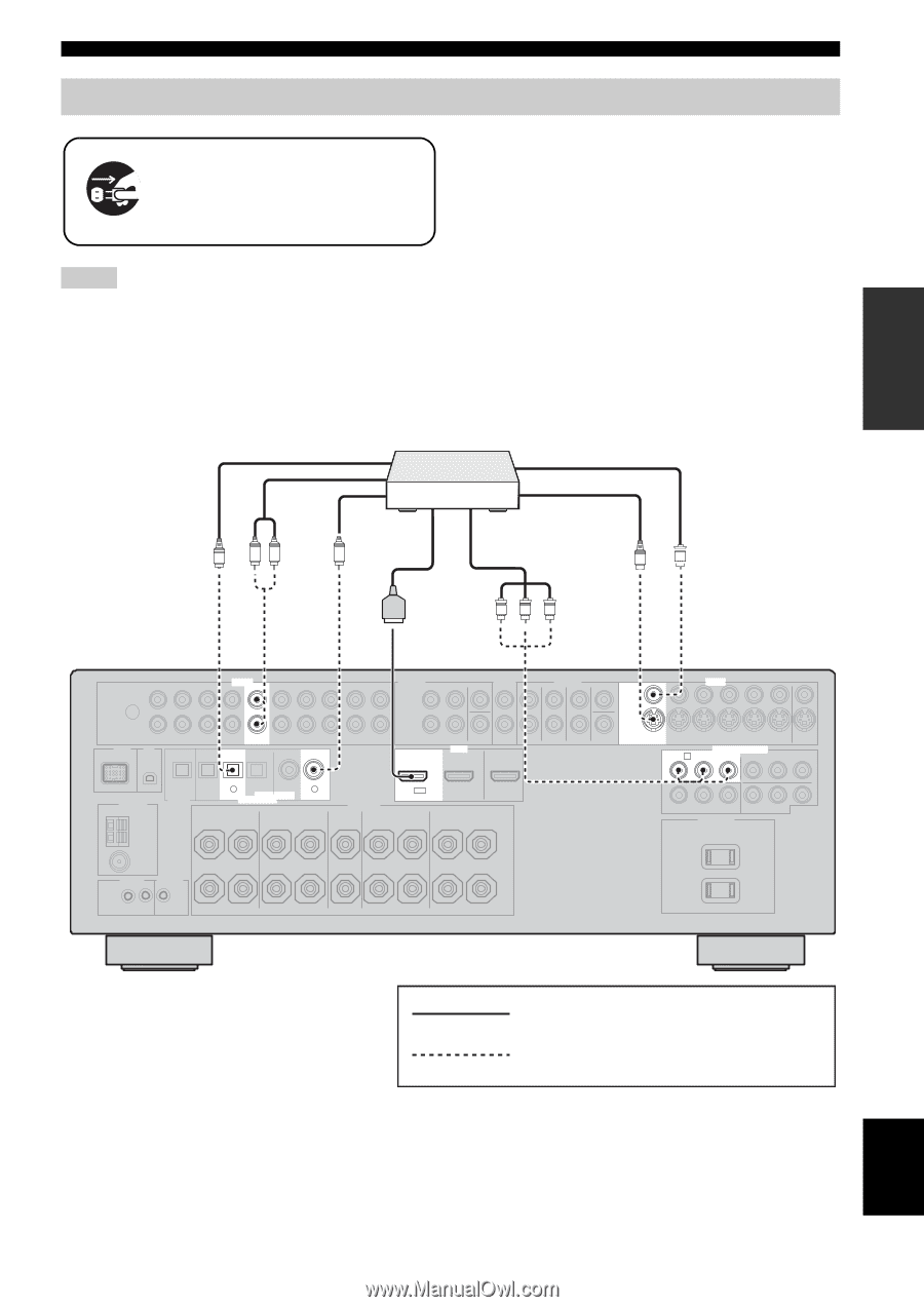
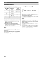
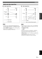
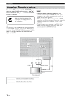
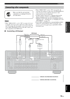
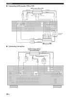
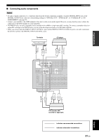
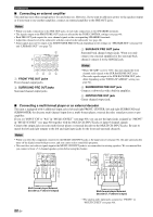
PREPARATION Connections Connecting other components Make sure that this unit and other components are unplugged from the AC wall outlets. Notes • When "VIDEO CONV." is set to "OFF" (see page 81), be sure to make the same type of video connections as those made for your TV (see page 18). For example, if you connected your TV to the VIDEO MONITOR OUT jack of this unit, connect your other components to the VIDEO jacks. • When "VIDEO CONV." is set to "ON" (see page 81), the converted video signals are output only at the MONITOR OUT jacks. To record a source, make the same type of video connections between each component. • To make a digital connection to a component other than the default component assigned to each DIGITAL INPUT or DIGITAL OUTPUT jack, select the corresponding setting for "OPTICAL OUT", "OPTICAL IN", or "COAXIAL IN" in "I/O ASSIGNMENT" (see page 78). • If you connect your DVD player to both the DIGITAL INPUT (OPTICAL) and the DIGITAL INPUT (COAXIAL) jacks, priority is given to the signals input at the DIGITAL INPUT (COAXIAL) jack. ■ Connecting a DVD player Optical out Audio out Coaxial out DVD player Video out S-video out HDMI out Component video out RL C S V O PR PB Y AUDIO DVD DVD DVD 3 6 OPTICAL COAXIAL DIGITAL INPUT HDMI DVD IN1 VIDEO VIDEO S VIDEO DVD PR COMPONENT VIDEO A DVD PB Y indicates recommended connections indicates alternative connections English 19 En
-
 1
1 -
2
-
3
-
4
-
5
-
6
-
7
-
8
-
9
-
10
-
11
-
12
-
13
-
14
-
15
-
16
-
17
-
 18
18 -
 19
19 -
 20
20 -
 21
21 -
 22
22 -
 23
23 -
 24
24 -
 25
25 -
 26
26 -
 27
27 -
 28
28 -
29
-
30
-
31
-
32
-
33
-
34
-
35
-
36
-
37
-
38
-
39
-
40
-
41
-
42
-
43
-
44
-
45
-
46
-
47
-
48
-
49
-
50
-
51
-
52
-
53
-
54
-
55
-
56
-
57
-
58
-
59
-
60
-
61
-
62
-
63
-
64
-
65
-
66
-
67
-
68
-
69
-
70
-
71
-
72
-
73
-
74
-
75
-
76
-
77
-
78
-
79
-
80
-
81
-
82
-
83
-
84
-
85
-
86
-
87
-
88
-
89
-
90
-
91
-
92
-
93
-
94
-
95
-
96
-
97
-
98
-
99
-
100
-
101
-
102
-
103
-
104
-
105
-
106
-
107
-
108
-
109
-
110
-
111
-
112
-
113
-
114
-
115
-
116
-
117
-
118
-
119
-
120
-
121
-
122
-
123
-
124
-
125
-
126
-
127
-
128
-
129
-
130
 |
 |