Yamaha RX V661 MCXSP10 Manual - Page 28
Connecting the FM and AM antennas, Connecting the power cable, AC OUTLETS SWITCHED - australia
 |
UPC - 027108927411
View all Yamaha RX V661 manuals
Add to My Manuals
Save this manual to your list of manuals |
Page 28 highlights
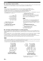
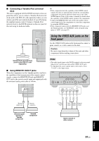
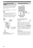
Connections Connecting the FM and AM antennas Both FM and AM indoor antennas are supplied with this unit. Connect each antenna correctly to the designated terminals. In general, these antennas should provide sufficient signal strength. y See page 8 for connection information of the supplied indoor FM antenna and AM loop antenna. Notes • The AM loop antenna should be placed away from this unit. • The AM loop antenna should always be connected, even if an outdoor AM antenna is connected to this unit. • A properly installed outdoor antenna provides clearer reception than an indoor one. If you experience poor reception quality, install an outdoor antenna. Consult the nearest authorized Yamaha dealer or service center about outdoor antennas. Connecting the power cable (U.S.A. model) AC OUTLETS To the AC wall outlet AM loop antenna (supplied) ANTENNA AM GND FM Indoor FM antenna (supplied) Outdoor AM antenna Use a 5 to 10 m (16 to 33 ft) vinyl-covered wire extended outdoors from a window. Ground (GND terminal) For maximum safety and minimum interference, connect the antenna GND terminal to a good earth ground. A good earth ground is a metal stake driven into moist earth. ■ AC OUTLET(S) (SWITCHED) U.K. and Australia models 1 outlet Korea model None Other models 2 outlets Use these outlet(s) to supply power to any connected components. Connect the power cable of your other components to these outlet(s). Power to these outlet(s) is supplied when the main zone or Zone 2 is turned on. However, power to these outlet(s) is cut off when the main zone and Zone 2 are turned off or when BMASTER ON/ OFF on the front panel is pressed and released outward to the OFF position. For information on the maximum power or the total power consumption of the components that can be connected to these outlet(s), see "Specifications" on page 108. Memory back-up The memory back-up circuit prevents the stored data from being lost even if this unit is in the standby mode. However, the stored data will be lost in case the power cable is disconnected from the AC wall outlet or if the power supply is cut off for more than one week. 24 En
-
 1
1 -
2
-
3
-
4
-
5
-
6
-
7
-
8
-
9
-
10
-
11
-
12
-
13
-
14
-
15
-
16
-
17
-
18
-
19
-
20
-
21
-
22
-
 23
23 -
 24
24 -
 25
25 -
 26
26 -
 27
27 -
 28
28 -
 29
29 -
 30
30 -
 31
31 -
 32
32 -
 33
33 -
34
-
35
-
36
-
37
-
38
-
39
-
40
-
41
-
42
-
43
-
44
-
45
-
46
-
47
-
48
-
49
-
50
-
51
-
52
-
53
-
54
-
55
-
56
-
57
-
58
-
59
-
60
-
61
-
62
-
63
-
64
-
65
-
66
-
67
-
68
-
69
-
70
-
71
-
72
-
73
-
74
-
75
-
76
-
77
-
78
-
79
-
80
-
81
-
82
-
83
-
84
-
85
-
86
-
87
-
88
-
89
-
90
-
91
-
92
-
93
-
94
-
95
-
96
-
97
-
98
-
99
-
100
-
101
-
102
-
103
-
104
-
105
-
106
-
107
-
108
-
109
-
110
-
111
-
112
-
113
-
114
-
115
-
116
-
117
-
118
-
119
-
120
-
121
-
122
-
123
-
124
-
125
-
126
-
127
-
128
-
129
-
130
 |
 |
