Canon VB-S30VE User Manual - Page 163
Configuring Detection Criteria ([Detection Criteria] Tab), column in [Non-detection Area Settings].
 |
View all Canon VB-S30VE manuals
Add to My Manuals
Save this manual to your list of manuals |
Page 163 highlights
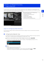
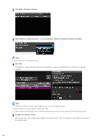
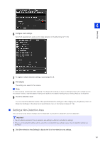
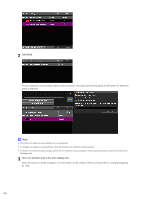
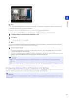
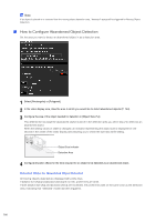
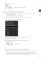
Setting Page 4 Note • You can create a polygonal area with a maximum of 32 vertices. You cannot set a non-detection area with only a straight line. • Click [Clear Area] to set the non-detection area again. • Enter [Non-detection Area Name (within 64 half-width alphanumeric characters)] as necessary. • The non-detection area is displayed in the video display area in black. The display color cannot be selected. 4 To register multiple non-detection areas, repeat steps 2 and 3. 5 Click [Apply]. The settings are saved in the camera. Note Click [Clear] to discard the settings and restore the settings saved in the camera. However, note that non-detection areas only added to the non-detection areas by clicking [Add] are all discarded. 6 Check the detection result. The status of the specified non-detection settings can be checked in the video display area and the [Status] column in [Non-detection Area Settings]. If [Enable non-detection area] is cleared, [Disabled] is displayed for the [Status] column in [Non-detection Area Settings], and the non-detection area is not displayed in the video display area. Important • Make sure to check the video display area to see whether the detection area and non-detection area are unintentionally overlapped. • If you set the detection area and non-detection area close to each other, detection may be performed incorrectly. Configuring Detection Criteria ([Detection Criteria] Tab) Detection criteria is controlled and set in the video display area for each type of detection. Important It is recommended that you configure the detection criteria in conditions as close as possible to the actual conditions in which you will use the camera. 163
-
 1
1 -
2
-
3
-
4
-
5
-
6
-
7
-
8
-
9
-
10
-
11
-
12
-
13
-
14
-
15
-
16
-
17
-
18
-
19
-
20
-
21
-
22
-
23
-
24
-
25
-
26
-
27
-
28
-
29
-
30
-
31
-
32
-
33
-
34
-
35
-
36
-
37
-
38
-
39
-
40
-
41
-
42
-
43
-
44
-
45
-
46
-
47
-
48
-
49
-
50
-
51
-
52
-
53
-
54
-
55
-
56
-
57
-
58
-
59
-
60
-
61
-
62
-
63
-
64
-
65
-
66
-
67
-
68
-
69
-
70
-
71
-
72
-
73
-
74
-
75
-
76
-
77
-
78
-
79
-
80
-
81
-
82
-
83
-
84
-
85
-
86
-
87
-
88
-
89
-
90
-
91
-
92
-
93
-
94
-
95
-
96
-
97
-
98
-
99
-
100
-
101
-
102
-
103
-
104
-
105
-
106
-
107
-
108
-
109
-
110
-
111
-
112
-
113
-
114
-
115
-
116
-
117
-
118
-
119
-
120
-
121
-
122
-
123
-
124
-
125
-
126
-
127
-
128
-
129
-
130
-
131
-
132
-
133
-
134
-
135
-
136
-
137
-
138
-
139
-
140
-
141
-
142
-
143
-
144
-
145
-
146
-
147
-
148
-
149
-
150
-
151
-
152
-
153
-
154
-
155
-
156
-
157
-
 158
158 -
 159
159 -
 160
160 -
 161
161 -
 162
162 -
 163
163 -
 164
164 -
 165
165 -
 166
166 -
 167
167 -
 168
168 -
169
-
170
-
171
-
172
-
173
-
174
-
175
-
176
-
177
-
178
-
179
-
180
-
181
-
182
-
183
-
184
-
185
-
186
-
187
-
188
-
189
-
190
-
191
-
192
-
193
-
194
-
195
-
196
-
197
-
198
-
199
-
200
-
201
-
202
-
203
-
204
-
205
-
206
-
207
-
208
-
209
-
210
-
211
-
212
-
213
-
214
-
215
-
216
-
217
-
218
-
219
-
220
-
221
-
222
-
223
-
224
-
225
-
226
-
227
-
228
-
229
-
230
-
231
-
232
-
233
-
234
-
235
-
236
-
237
-
238
 |
 |