Dell IP4700 Service Guide - Page 30
Link Control Cards (LCCs), failover, that is, an automatic transfer of one or more file systems
 |
View all Dell IP4700 manuals
Add to My Manuals
Save this manual to your list of manuals |
Page 30 highlights
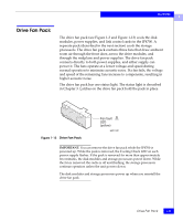
The IP4700 1 Link Control Cards (LCCs) A link control card (see Figure 1-8) connects Fibre Channel signalling to the disk modules. The link control card provides • Fibre Channel connectivity between the storage processor, disks, and other enclosures • Bypass capability for faulted or missing units • Monitor and control of the enclosure elements Active LED (green) Expansion FC-AL cable connector (EXP) Fault LED (amber) EMC1458 Figure 1-8 Link Control Card Each link control card independently monitors the environmental status of the entire IP4700, using a microcomputer-controlled customer-replaceable unit (CRU) monitor. The CRU monitor communicates status to the storage processor server using special protocols. These protocols let the storage processor poll IP4700 status and send commands that control the disk-module check lights. Each link control card has two status LEDs visible from the back of the IP4700. For the meaning of these LEDs, see the Monitoring IP4700 Status section in Chapter 3. A latch on the link control card locks it into place to ensure proper connection to the midplane. You can add or replace a link control card while the IP4700 is powered up. ! CAUTION Removing a link control card or storage processor will cause a failover, that is, an automatic transfer of one or more file systems from one storage processor to another. 1-12 IP4700 Installation and Service Guide
-
 1
1 -
2
-
3
-
4
-
5
-
6
-
7
-
8
-
9
-
10
-
11
-
12
-
13
-
14
-
15
-
16
-
17
-
18
-
19
-
20
-
21
-
22
-
23
-
24
-
 25
25 -
 26
26 -
 27
27 -
 28
28 -
 29
29 -
 30
30 -
 31
31 -
 32
32 -
 33
33 -
 34
34 -
 35
35 -
36
-
37
-
38
-
39
-
40
-
41
-
42
-
43
-
44
-
45
-
46
-
47
-
48
-
49
-
50
-
51
-
52
-
53
-
54
-
55
-
56
-
57
-
58
-
59
-
60
-
61
-
62
-
63
-
64
-
65
-
66
-
67
-
68
-
69
-
70
-
71
-
72
-
73
-
74
-
75
-
76
-
77
-
78
-
79
-
80
-
81
-
82
-
83
-
84
-
85
-
86
-
87
-
88
-
89
-
90
-
91
-
92
-
93
-
94
-
95
-
96
-
97
-
98
-
99
-
100
-
101
-
102
-
103
-
104
-
105
-
106
-
107
-
108
-
109
-
110
-
111
-
112
-
113
-
114
-
115
-
116
-
117
-
118
-
119
-
120
-
121
-
122
-
123
-
124
-
125
-
126
 |
 |
