Dell IP4700 Service Guide - Page 38
Requirements, Cabling
 |
View all Dell IP4700 manuals
Add to My Manuals
Save this manual to your list of manuals |
Page 38 highlights
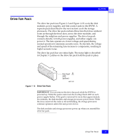
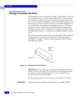
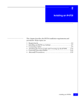
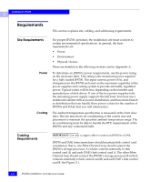
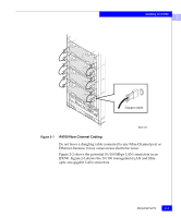
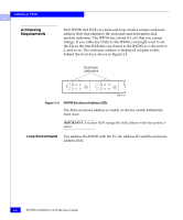
Installing an IP4700 2 Requirements This section explains site, cabling, and addressing requirements. Site Requirements Power Cooling For proper IP4700 operation, the installation site must conform to certain environmental specifications. In general, the basic requirements are • Power • Environment • Physical/Access These are detailed in the following sections and in Appendix A. To determine an IP4700's power requirements, use the power rating on the enclosure label. This rating is the maximum power required for a fully loaded IP4700. The input current, power (VA), and dissipation for the IP4700 are based on the maximum capability of the power supplies and cooling system to provide internally regulated power. Typical values will be less, depending on the number and manufacturer of disk drives. If one of the two power supplies fails, the remaining power supply supports the full load. You must use a rackmount cabinet with ac power distribution, and have main branch ac distribution that can handle these power values for the number of IP4700s and DAEs that you will interconnect. The ambient temperature specification is measured at the front door inlet. The site must have air conditioning of the correct size and placement to maintain the specified ambient temperature range. The air conditioning must be able to handle the BTU requirements of the IP4700s and any connected DAEs. Cabling Requirements IMPORTANT: Use only a copper cable to connect an IP4700 to a DAE. IP4700 and DAE interconnections should maintain link control card consistency; that is, one Fibre Channel loop should connect the IP4700's storage processor A (which connects internally to link control card A) and each DAE's link control card A. The other Fibre Channel loop should connect the IP4700's storage processor B (which connects internally to link control card B) and each DAE's link control card B. See Figure 2-1. 2-2 IP4700 Installation and Service Guide
-
 1
1 -
2
-
3
-
4
-
5
-
6
-
7
-
8
-
9
-
10
-
11
-
12
-
13
-
14
-
15
-
16
-
17
-
18
-
19
-
20
-
21
-
22
-
23
-
24
-
25
-
26
-
27
-
28
-
29
-
30
-
31
-
32
-
 33
33 -
 34
34 -
 35
35 -
 36
36 -
 37
37 -
 38
38 -
 39
39 -
 40
40 -
 41
41 -
 42
42 -
 43
43 -
44
-
45
-
46
-
47
-
48
-
49
-
50
-
51
-
52
-
53
-
54
-
55
-
56
-
57
-
58
-
59
-
60
-
61
-
62
-
63
-
64
-
65
-
66
-
67
-
68
-
69
-
70
-
71
-
72
-
73
-
74
-
75
-
76
-
77
-
78
-
79
-
80
-
81
-
82
-
83
-
84
-
85
-
86
-
87
-
88
-
89
-
90
-
91
-
92
-
93
-
94
-
95
-
96
-
97
-
98
-
99
-
100
-
101
-
102
-
103
-
104
-
105
-
106
-
107
-
108
-
109
-
110
-
111
-
112
-
113
-
114
-
115
-
116
-
117
-
118
-
119
-
120
-
121
-
122
-
123
-
124
-
125
-
126
 |
 |
