Dell IP4700 Service Guide - Page 33
connection to the midplane., described
 |
View all Dell IP4700 manuals
Add to My Manuals
Save this manual to your list of manuals |
Page 33 highlights
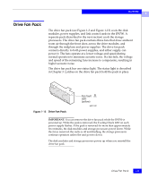
The IP4700 1 removed. The status LEDs are shown in Figure 1-11, and further described in Chapter 3. A latch on the power supply locks it into place to ensure proper connection to the midplane. Active LED (green) Fault LED (amber) Cooling check LED (amber) Figure 1-11 Rear View of the Power Supply AC power connector On/off switch and circuit breaker EMC1453 Power Supplies 1-15
-
 1
1 -
2
-
3
-
4
-
5
-
6
-
7
-
8
-
9
-
10
-
11
-
12
-
13
-
14
-
15
-
16
-
17
-
18
-
19
-
20
-
21
-
22
-
23
-
24
-
25
-
26
-
27
-
 28
28 -
 29
29 -
 30
30 -
 31
31 -
 32
32 -
 33
33 -
 34
34 -
 35
35 -
 36
36 -
 37
37 -
 38
38 -
39
-
40
-
41
-
42
-
43
-
44
-
45
-
46
-
47
-
48
-
49
-
50
-
51
-
52
-
53
-
54
-
55
-
56
-
57
-
58
-
59
-
60
-
61
-
62
-
63
-
64
-
65
-
66
-
67
-
68
-
69
-
70
-
71
-
72
-
73
-
74
-
75
-
76
-
77
-
78
-
79
-
80
-
81
-
82
-
83
-
84
-
85
-
86
-
87
-
88
-
89
-
90
-
91
-
92
-
93
-
94
-
95
-
96
-
97
-
98
-
99
-
100
-
101
-
102
-
103
-
104
-
105
-
106
-
107
-
108
-
109
-
110
-
111
-
112
-
113
-
114
-
115
-
116
-
117
-
118
-
119
-
120
-
121
-
122
-
123
-
124
-
125
-
126
 |
 |

1
Power Supplies
1-15
The IP4700
removed. The status LEDs are shown in Figure 1-11, and further
described in Chapter 3.
A latch on the power supply locks it into place to ensure proper
connection to the midplane.
Figure 1-11
Rear View of the Power Supply
EMC1453
Active
LED
(green)
Fault
LED
(amber)
Cooling
check LED
(amber)
AC power
connector
On/off switch
and circuit
breaker