Dell IP4700 Service Guide - Page 55
position. See Turn the power switch on each SPS to the on position. See
 |
View all Dell IP4700 manuals
Add to My Manuals
Save this manual to your list of manuals |
Page 55 highlights
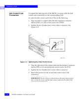
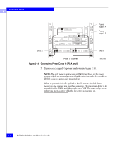
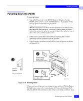
Installing an IP4700 2 8. Reinstall the drive fan pack in the back of the IP4700. NOTE: You can install the drive fan pack in either horizontal position. However, to maintain consistency with the DAEs, we recommend you install it with the fault LED in the upper right corner, as shown in Figure 2-17. Fan fault LED (yellow) EMC1451 Figure 2-17 Installing the Drive Fan Pack 9. In the cabinet, set the main circuit breaker switches to the on position. See Figure 2-18. 10. Turn the power switch on each SPS to the on position. See Figure 2-18. The IP4700 and any DAEs in the cabinet will power up. Attaching the Power Cords and Powering Up the IP4700 2-19
-
 1
1 -
2
-
3
-
4
-
5
-
6
-
7
-
8
-
9
-
10
-
11
-
12
-
13
-
14
-
15
-
16
-
17
-
18
-
19
-
20
-
21
-
22
-
23
-
24
-
25
-
26
-
27
-
28
-
29
-
30
-
31
-
32
-
33
-
34
-
35
-
36
-
37
-
38
-
39
-
40
-
41
-
42
-
43
-
44
-
45
-
46
-
47
-
48
-
49
-
 50
50 -
 51
51 -
 52
52 -
 53
53 -
 54
54 -
 55
55 -
 56
56 -
 57
57 -
 58
58 -
 59
59 -
 60
60 -
61
-
62
-
63
-
64
-
65
-
66
-
67
-
68
-
69
-
70
-
71
-
72
-
73
-
74
-
75
-
76
-
77
-
78
-
79
-
80
-
81
-
82
-
83
-
84
-
85
-
86
-
87
-
88
-
89
-
90
-
91
-
92
-
93
-
94
-
95
-
96
-
97
-
98
-
99
-
100
-
101
-
102
-
103
-
104
-
105
-
106
-
107
-
108
-
109
-
110
-
111
-
112
-
113
-
114
-
115
-
116
-
117
-
118
-
119
-
120
-
121
-
122
-
123
-
124
-
125
-
126
 |
 |

2
Attaching the Power Cords and Powering Up the IP4700
2-19
Installing an IP4700
8.
Reinstall the drive fan pack in the back of the IP4700.
NOTE:
You can install the drive fan pack in either horizontal position.
However, to maintain consistency with the DAEs, we recommend you
install it with the fault LED in the upper right corner, as shown in
Figure 2-17.
Figure 2-17
Installing the Drive Fan Pack
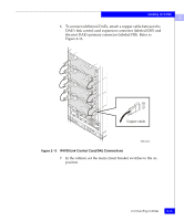
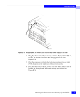
9.
In the cabinet, set the main circuit breaker switches to the on
position. See Figure 2-18.
10.
Turn the power switch on each SPS to the on position. See
Figure 2-18.
The IP4700 and any DAEs in the cabinet will power up.
EMC1451
Fan fault
LED
(yellow)