Dell Latitude CP Replacement Instructions
Dell Latitude CP Manual
 |
View all Dell Latitude CP manuals
Add to My Manuals
Save this manual to your list of manuals |
Dell Latitude CP manual content summary:
- Dell Latitude CP | Replacement Instructions - Page 1
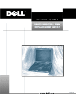
Place art inside this frame. You may resize the frame to accomodate the art if necessary. Make sure you size the art all the way to the edges of the frame. - Dell Latitude CP | Replacement Instructions - Page 2
rights reserved. Reproduction in any manner whatsoever without the written permission of Dell Computer Corporation is strictly forbidden. Trademarks used in this text: Dell, the DELL logo, and Latitude are trademarks of Dell Computer Corporation. Other trademarks and trade names may be used in this - Dell Latitude CP | Replacement Instructions - Page 3
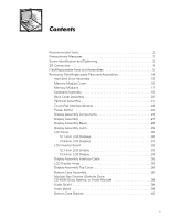
Parts and Assemblies 14 Hard-Disk Drive Assembly 15 Memory Module Cover 16 Memory Modules 17 Keyboard Assembly 18 Back Cover Assembly 20 Palmrest Assembly 21 Touch-Pad Interface Module 23 Power (Diskette Drive, CD-ROM Drive, Battery, or Travel Module 38 Audio Shield 38 Audio Board 39 - Dell Latitude CP | Replacement Instructions - Page 4
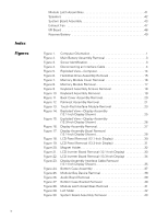
. Figure 29. Figure 30. Computer Orientation 1 Main Battery Assembly Removal 3 Screw Identification 3 Disconnecting an Interface Cable 4 Exploded View-Computer 14 Hard-Disk Drive Assembly Removal 15 Memory Module Cover Removal 16 Memory Module Removal 17 Keyboard Assembly Screws Removal 18 - Dell Latitude CP | Replacement Instructions - Page 5
Figure 31. Figure 32. Figure 33. Figure 34. Figure 35. One- and Two-Slot Processor Hold-Down Clips 45 Processor Module 46 Exhaust Fan Removal 47 I/R Board Removal 48 Reserve Battery Installation 49 Table 1. Parts and Assemblies 5 v - Dell Latitude CP | Replacement Instructions - Page 6
techniques. In addition to information provided in this manual and the online Systems User's Guide that came with the system, Dell provides the Diagnostics and Troubleshooting Guide for troubleshooting procedures and instructions on using the Dell diagnostics to test the computer system. Throughout - Dell Latitude CP | Replacement Instructions - Page 7
to exceed 180 degrees. Also, when performing the procedures in this guide, the locations or directions relative to the computer are as shown in Figure 1 unless otherwise specified. back of computer left side right side front of computer Dell Latitude CP and CPi - Parts Removal and Replacement - Dell Latitude CP | Replacement Instructions - Page 8
out of the modular bay with the other hand. 9. Remove the main battery assembly from the battery bay. Slide the battery bay latch away from the center of the computer. Then slide the battery out of the battery bay (see Figure 2). 2 Dell Latitude CP and CPi - Parts Removal and Replacement Guide - Dell Latitude CP | Replacement Instructions - Page 9
procedures provide the correct screw length as part of the screw's label. A graphic for that length screw is also included in the illustration. Match the actual screw to the graphic in the illustration to check for correct length. Dell Latitude CP and CPi - Parts Removal and Replacement Guide 3 - Dell Latitude CP | Replacement Instructions - Page 10
ZIF connector, follow these steps: 1. Use a small flat-blade screwdriver to open the movable part of the ZIF connector. 2. Orient the end of the interface cable with the ZIF connector, sure the ZIF connector is completely closed. 4 Dell Latitude CP and CPi - Parts Removal and Replacement Guide - Dell Latitude CP | Replacement Instructions - Page 11
,MN,14.4V,8CELL, 2 LITH Main battery BTRY,MN,14.4V,8CELL,LITH Service kit, reserve battery SVC,BTRY,RSRV,7.2V,30MAH,6, 35 NIHD Reserve battery BTRY,RSRV,7.2V,30MAH,6, NIHD Reserve battery sponge PAD,FOAM,BRTY,RSRV,CP pad Dell Latitude CP and CPi - Parts Removal and Replacement Guide 5 - Dell Latitude CP | Replacement Instructions - Page 12
FD,F3,CP top cover Diskette drive assembly PWA,INTFC,FD,F3,CP interface board Diskette drive assembly CBL,FPC,FD,F3,CP interface cable Diskette drive assembly SHLD,FD,F3,CP shield Service kit, exhaust fan SVC,FAN,25X25X10,CP 33 6 Dell Latitude CP and CPi - Parts Removal and Replacement Guide - Dell Latitude CP | Replacement Instructions - Page 13
,87,KOR,CP Keyboard, Latin American KYBD,88,LAC,CP Keyboard, Norwegian KYBD,88,NOR,CP Keyboard, Portuguese KYBD,88,PORTUGEUSE,CP * Substitute the drive capacity for xxxxx, the drive height for yy, and the manufacturer for zzz. Dell Latitude CP and CPi - Parts Removal and Replacement Guide 7 - Dell Latitude CP | Replacement Instructions - Page 14
EMI shield SVC,BZL,LCD,12.1",CP BZL,LCD,TFT,12.1",CP CVR,SCR,TOP,RND,ADH CVR,SCR,BTM,OVAL,ADH CVR,SCR,TOP,OVAL,SM,ADH,12.1 SVC,ASSY,CVR,TOP,LCD, 12.1",CP CVR,TOP,LCD,TFT,12.1",CP SHLD,EMI,DIS,TFT/STN, 12.1",CP 14, 17 8 Dell Latitude CP and CPi - Parts Removal and Replacement Guide - Dell Latitude CP | Replacement Instructions - Page 15
covers, lower Display-assembly-bezel retaining screw covers, latch, 13.3-inch display SVC,BZL,LCD,13.3",CPX BZL,LCD,TFT,13.3",CPX CVR,SCR,LCD,13.3",TOP, OVAL,CPX CVR,SCR,BTM,RND,ADH BMPR,RBR,UPR,LCD,13.3", NBK,CPX 14, 18 15, 17 Dell Latitude CP and CPi - Parts Removal and Replacement Guide 9 - Dell Latitude CP | Replacement Instructions - Page 16
, SUBASSY,CBL/HLDR,TFT, Sharp SHARP,CP LCD panel, Sharp LCD,TFT,XGA,13.3",CP,SHARP Latch service kit, 12.1-inch SVC,LATCH,DIS,BZL,CP 14 LCD display Latch service kit, 13.3-inch SVC,LATCH,DIS,BZL,CPX 15 LCD display 10 Dell Latitude CP and CPi - Parts Removal and Replacement Guide - Dell Latitude CP | Replacement Instructions - Page 17
, MEM/BIOS,NB,CP Touch-pad bracket Air flow duct BRCKT,TPAD,CP 13 GDE,INTK,AIR,FAN,PLSTC,CP 30 Service kit, palmrest SVC,SUBASSY,PLMRST,CP 12 assembly Palmrest assembly ASSY,PLMRST,GRY,CP Power button SWT,PWR SW, CP Power button spring SPR,PWR SW,CP Dell Latitude CP and CPi - Parts - Dell Latitude CP | Replacement Instructions - Page 18
, hard-disk drive SCR Service tag install disk DISK,FLD SERV,F3,US,LXP System board assembly with system board and processor module ASSY,PRM/PWA,ENGINE, CPxxx* * Substitute the drive capacity for xxxxx, the drive height for yy, and the manufacturer for zzz. 12 Dell Latitude CP and CPi - Parts - Dell Latitude CP | Replacement Instructions - Page 19
SVC,SUBASSY,HTSNK, 30 subassembly CPU,HYB,CP Touch-pad service kit SVC,TPAD,SQ,INTFC,CP 13 Touch-pad subassembly TPA,INTFC,CP * Substitute the drive capacity for xxxxx, the drive height for yy, and the manufacturer for zzz. Dell Latitude CP and CPi - Parts Removal and Replacement Guide 13 - Dell Latitude CP | Replacement Instructions - Page 20
assembly keyboard palmrest assembly back cover assembly main battery modular bay device bottom case assembly The following subsections provide instructions for removing and replacing field-replaceable parts and assemblies. 14 Dell Latitude CP and CPi - Parts Removal and Replacement Guide - Dell Latitude CP | Replacement Instructions - Page 21
mm screws (2) hard-disk drive door 1. Turn the computer over, and remove the two 5-mm screws from the hard-disk drive door. The drive is on the left side of the computer. 2. Grasp the drive door and pull the drive out of the computer. Dell Latitude CP and CPi - Parts Removal and Replacement Guide 15 - Dell Latitude CP | Replacement Instructions - Page 22
down on a flat work surface. 2. Release the memory module cover. Insert a fingertip in the indentation in the bottom case assembly and lift the cover slightly; then slide the cover in the direction indicated by the arrow on the cover. 16 Dell Latitude CP and CPi - Parts Removal and Replacement Guide - Dell Latitude CP | Replacement Instructions - Page 23
out of its socket. Memory modules can be installed only one way. Do not attempt to force the memory module into the socket. Align the notch near the center of the memory module with the corresponding key in the memory module socket. Dell Latitude CP and CPi - Parts Removal and Replacement Guide 17 - Dell Latitude CP | Replacement Instructions - Page 24
or a small flat-bladed screwdriver under the scalloped edge of the blank key (see Figure 10), and lift the right edge of the keyboard. 18 Dell Latitude CP and CPi - Parts Removal and Replacement Guide - Dell Latitude CP | Replacement Instructions - Page 25
the keyboard is correctly installed. The keys should be flush with the left and right surfaces of the palmrest. 5. Reinstall the six 12-mm screws. Dell Latitude CP and CPi - Parts Removal and Replacement Guide 19 - Dell Latitude CP | Replacement Instructions - Page 26
right end of the back cover assembly firmly, and unsnap it from the computer. Then disengage the left end of the back cover assembly. 20 Dell Latitude CP and CPi - Parts Removal and Replacement Guide - Dell Latitude CP | Replacement Instructions - Page 27
, adjacent to the thermal cooling assembly Two 5-mm screws inside the upper edge of the hard-disk drive bay (you must remove the hard-disk drive to access these screws) Three 12-mm screws underneath the front edge of the computer Dell Latitude CP and CPi - Parts Removal and Replacement Guide 21 - Dell Latitude CP | Replacement Instructions - Page 28
-side up on the work surface, and open the display assembly 180 degrees. NOTE: Support the display assembly with a book or similar object so that the display assembly does not EMI shield and is fitted within the palmrest assembly. 22 Dell Latitude CP and CPi - Parts Removal and Replacement Guide - Dell Latitude CP | Replacement Instructions - Page 29
cable from ZIF connector J1 on the touch-pad interface module. To release the ZIF connector latch, use a fingernail to lift up the central portion of the black plastic latch. 5. Remove the touch-pad interface module from the palmrest. Dell Latitude CP and CPi - Parts Removal and Replacement Guide 23 - Dell Latitude CP | Replacement Instructions - Page 30
down on a flat work surface. 3. Compress the two catches securing the power button, and remove the power button and spring from the palmrest assembly. For removal purposes, the display assembly right bracket (12.1-inch display only) 24 Dell Latitude CP and CPi - Parts Removal and Replacement Guide - Dell Latitude CP | Replacement Instructions - Page 31
display assembly bezel LCD panel display-assembly interface cable display-assembly top-cover assembly hinges (2) display assembly latch right bracket LCD inverter board Dell Latitude CP and CPi - Parts Removal and Replacement Guide 25 - Dell Latitude CP | Replacement Instructions - Page 32
display assembly bezel LCD panel display-assembly interface cable display-assembly top-cover assembly hinge (2) display assembly latch LCD inverter board shield LCD inverter board 26 Dell Latitude CP and CPi - Parts Removal and Replacement Guide - Dell Latitude CP | Replacement Instructions - Page 33
the grounding tabs and pull the connector straight up from the system board. 4. Close the display, being careful not to damage the display interface cable. Dell Latitude CP and CPi - Parts Removal and Replacement Guide 27 - Dell Latitude CP | Replacement Instructions - Page 34
and the LCD panel, and lift upward on the bezel to release the hidden snaps. Avoid pressing on the surface of the LCD panel. 28 Dell Latitude CP and CPi - Parts Removal and Replacement Guide - Dell Latitude CP | Replacement Instructions - Page 35
cover. b. If replacing the latch in a 13.3-inch display, unsnap the latch and captive spring from the inside of the display assembly top-cover assembly. Dell Latitude CP and CPi - Parts Removal and Replacement Guide 29 - Dell Latitude CP | Replacement Instructions - Page 36
Remove the four silver 5-mm screws at the corners of the LCD panel. 3. Disconnect the LCD panel power cable from connector J2 on the LCD inverter board. 4. Lift the left edge of the LCD panel on the underside of the LCD panel. 30 Dell Latitude CP and CPi - Parts Removal and Replacement Guide - Dell Latitude CP | Replacement Instructions - Page 37
LCD panel interface cable magnet holder interface cable connector LCD inverter board LCD panel power cable display-assembly top cover LCD inverter board shield 1. Remove the display assembly on the LCD interface cable itself. Dell Latitude CP and CPi - Parts Removal and Replacement Guide 31 - Dell Latitude CP | Replacement Instructions - Page 38
by checking the back of the LCD panel for the manufacturer's label, and then follow the instructions for that manufacturer. Sharp LCD Panel Some revisions of the Sharp LCD panel have a magnetic adequate grounding of the LCD panel.) 32 Dell Latitude CP and CPi - Parts Removal and Replacement Guide - Dell Latitude CP | Replacement Instructions - Page 39
cable to the board prior to securing the board in the display-assembly top cover. After installing the inverter board, ensure that the LCD-panel power cable is routed around the plastic screw bosses in the display-assembly top cover. Dell Latitude CP and CPi - Parts Removal and Replacement Guide 33 - Dell Latitude CP | Replacement Instructions - Page 40
shield. NOTE: Replace the LCD inverter board in the shield so that the components on the board face towards the display-assembly top cover. 34 Dell Latitude CP and CPi - Parts Removal and Replacement Guide - Dell Latitude CP | Replacement Instructions - Page 41
around the plastic bobbin before connecting the cable to the system board. 1. Remove the LCD display assembly from the computer. 2. Remove the display assembly bezel. Dell Latitude CP and CPi - Parts Removal and Replacement Guide 35 - Dell Latitude CP | Replacement Instructions - Page 42
marked by arrows on the face of each hinge. The bottom case assembly consists of the following field-replaceable components: Diskette drive assembly, CD-ROM drive assembly, or travel module Back cover assembly Audio shield Audio board 36 Dell Latitude CP and CPi - Parts Removal and Replacement Guide - Dell Latitude CP | Replacement Instructions - Page 43
Air flow duct Exhaust fan I/R board Reserve battery audio shield thermal cooling assembly I/R board system board assembly bottom case bracket module latch assembly (2) main battery audio board air flow duct modular bay device Dell Latitude CP and CPi - Parts Removal and Replacement Guide 37 - Dell Latitude CP | Replacement Instructions - Page 44
latch lock NOTE: You do not need to remove the main battery or hard-disk drive prior to this procedure. 1. Close the display and turn the computer over. 2. a device in the modular bay prior to reinstalling the palmrest assembly.) 38 Dell Latitude CP and CPi - Parts Removal and Replacement Guide - Dell Latitude CP | Replacement Instructions - Page 45
with devices installed in the modular bay. (You can check this by temporarily installing a device in the modular bay prior to reinstalling the palmrest assembly.) Dell Latitude CP and CPi - Parts Removal and Replacement Guide 39 - Dell Latitude CP | Replacement Instructions - Page 46
case bracket. 5. Insert the end of a small flat-bladed screwdriver into the slot in the vertical support in the center of the bottom case, and disengage the plastic retaining clip. 6. Lift the bottom clips on the bottom case bracket. 40 Dell Latitude CP and CPi - Parts Removal and Replacement Guide - Dell Latitude CP | Replacement Instructions - Page 47
latch assemblies (2) springs (2) module latches (2) 1. Remove the bottom case bracket. 2. Remove the left latch from the outside of slider. 4. Ensure that the newly installed latch moves smoothly and freely when pushed and released. Dell Latitude CP and CPi - Parts Removal and Replacement Guide 41 - Dell Latitude CP | Replacement Instructions - Page 48
the bottom case so that the speaker wires are facing upwards. Route the speaker wires under their retaining clips on the bottom case bracket. 42 Dell Latitude CP and CPi - Parts Removal and Replacement Guide - Dell Latitude CP | Replacement Instructions - Page 49
the service tag number to the replacement system board assembly. 1. Remove the palmrest assembly. 2. Remove the LCD display assembly. 3. Remove the audio board. 4. Remove the two 2.5-mm screws securing the thermal cooling subassembly to the microprocessor module. Dell Latitude CP and CPi - Parts - Dell Latitude CP | Replacement Instructions - Page 50
by carefully tipping the screwdriver away from the microprocessor module. c. If your computer has a two-slot hold-down clip (see Figure 31), repeat substeps a and b for the second slot. d. Lift the clip off the fence and discard it. 44 Dell Latitude CP and CPi - Parts Removal and Replacement Guide - Dell Latitude CP | Replacement Instructions - Page 51
fits on the left side of the module, in the notches. 9. Remove the air flow duct. 10. Verify that the PC Card ejectors do not extend from the PC Card bay. 11. Remove the 2.5-mm screw from the center of the computer's left rear foot. Dell Latitude CP and CPi - Parts Removal and Replacement Guide 45 - Dell Latitude CP | Replacement Instructions - Page 52
32. Press the clip down to lock it in place. Do not reuse the old clip. processor hold-down clip (one-slot clip shown) processor-module fence holes 46 Dell Latitude CP and CPi - Parts Removal and Replacement Guide - Dell Latitude CP | Replacement Instructions - Page 53
and the power cable is at the upper right corner of the fan (when viewed from the back of the computer). (This will prevent the fan wires from being pinched when you reassemble the computer.) Make sure that the wires are routed below the upper EMI shield. Dell Latitude CP and CPi - Parts Removal and - Dell Latitude CP | Replacement Instructions - Page 54
5-mm screw I/R board 1. Remove the palmrest assembly. 2. Remove the 5-mm screw securing the I/R board to the system board assembly. 3. Lift the I/R board straight up from the system board assembly. 48 Dell Latitude CP and CPi - Parts Removal and Replacement Guide - Dell Latitude CP | Replacement Instructions - Page 55
the system board assembly. NOTE: When replacing the reserve battery, first connect the reserve battery cable to the system board. Then position the reserve battery on the hard-disk drive bay so there is minimal slack in the cable. Dell Latitude CP and CPi - Parts Removal and Replacement Guide 49 - Dell Latitude CP | Replacement Instructions - Page 56
50 Dell Latitude CP and CPi - Parts Removal and Replacement Guide - Dell Latitude CP | Replacement Instructions - Page 57
cover, removal, 36 back cover assembly removal, 20 battery (in modular bay) removal, 38 bottom case assembly parts and assemblies illustrated, 14 list of, 5 cables display-assembly interface cable, removal, 35 CD-ROM drive removal, 38 hard-disk drive assembly removal, 15 diskette drive - Dell Latitude CP | Replacement Instructions - Page 58
board removal, 33, 34 LCD panel removal, 30, 31 screw identification and tightening, 3 sockets memory module, 17 speakers removal, 42 system board assembly removal, 43 main battery assembly removal, 2 memory module removal, 17 memory module cover removal, 16 modular bay devices removal, 38
-
 1
1 -
 2
2 -
 3
3 -
 4
4 -
 5
5 -
 6
6 -
 7
7 -
8
-
9
-
10
-
11
-
12
-
13
-
14
-
15
-
16
-
17
-
18
-
19
-
20
-
21
-
22
-
23
-
24
-
25
-
26
-
27
-
28
-
29
-
30
-
31
-
32
-
33
-
34
-
35
-
36
-
37
-
38
-
39
-
40
-
41
-
42
-
43
-
44
-
45
-
46
-
47
-
48
-
49
-
50
-
51
-
52
-
53
-
54
-
55
-
56
-
57
-
58
 |
 |

±±±²³´µµ²¶·¸
±
±²³³´µ¶·¸¹¸º»²´µ¼½µ·¾»µ¼½¹
±²³´µ¶³·¸¹º²»¶²¼½
³·±»²¾·¸·¼´¶¿ÀÁ½·
±²³´µ¶··¸
Place art inside this frame.
You may resize the frame
to accomodate the art if necessary.
Make sure you
size the art all the way to the edges of the frame.