Dell Latitude CP Replacement Instructions - Page 41
Display-Assembly Interface Cable, LCD Display Hinge
 |
View all Dell Latitude CP manuals
Add to My Manuals
Save this manual to your list of manuals |
Page 41 highlights
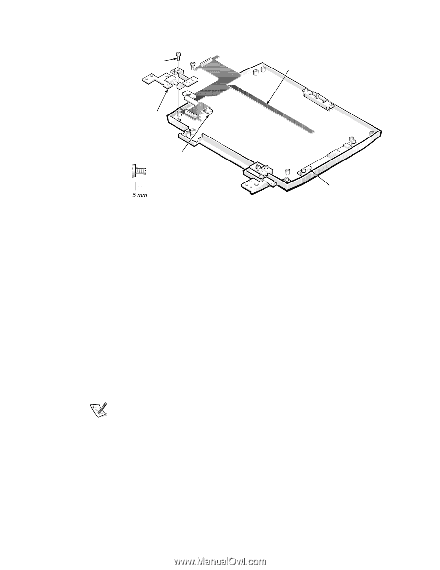
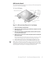
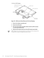
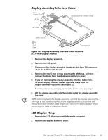
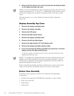
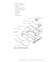
5-mm screws (2) left hinge plastic bobbin display-assembly interface cable connector J1 1. Remove the display assembly. 2. Remove the LCD panel. 3. Disconnect the display-assembly interface cable from ZIF connector J1 on the LCD inverter board. 4. Remove the two 5-mm screws securing the left hinge, and then remove the hinge from the display-assembly top cover. 5. If you are removing the display-assembly interface cable from a 13.3-inch display, remove the left top-cover brace from the display-assembly top cover (see Figure 22). To remove the top cover brace, remove the 3-mm screw securing it. 6. Lift the display-assembly interface cable out of the display-assembly top cover. NOTE: When replacing the display assembly, reinstall the screws securing the left hinge at the locations marked on the hinge by arrows. Ensure that the display-assembly interface cable wraps once around the plastic bobbin before connecting the cable to the system board. 1. Remove the LCD display assembly from the computer. 2. Remove the display assembly bezel. Dell Latitude CP and CPi - Parts Removal and Replacement Guide 35
-
 1
1 -
2
-
3
-
4
-
5
-
6
-
7
-
8
-
9
-
10
-
11
-
12
-
13
-
14
-
15
-
16
-
17
-
18
-
19
-
20
-
21
-
22
-
23
-
24
-
25
-
26
-
27
-
28
-
29
-
30
-
31
-
32
-
33
-
34
-
35
-
 36
36 -
 37
37 -
 38
38 -
 39
39 -
 40
40 -
 41
41 -
 42
42 -
 43
43 -
 44
44 -
 45
45 -
 46
46 -
47
-
48
-
49
-
50
-
51
-
52
-
53
-
54
-
55
-
56
-
57
-
58
 |
 |