Dell Latitude CP Replacement Instructions - Page 49
System Board Assembly, Remove the audio board. - latitude cpi bios
 |
View all Dell Latitude CP manuals
Add to My Manuals
Save this manual to your list of manuals |
Page 49 highlights
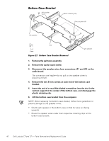
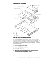
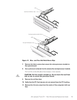
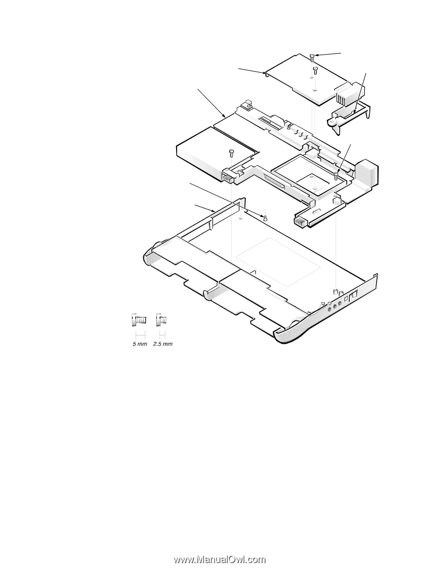
thermal cooling assembly system board assembly 2.5-mm screw bottom case assembly 2.5-mm screws (2) air flow duct 5-mm screws (2) The system board's BIOS chip contains the system service tag number, which is also visible on a bar-code label on the bottom of the computer. The replacement kit for the system board assembly includes a diskette that provides a utility for transferring the service tag number to the replacement system board assembly. 1. Remove the palmrest assembly. 2. Remove the LCD display assembly. 3. Remove the audio board. 4. Remove the two 2.5-mm screws securing the thermal cooling subassembly to the microprocessor module. Dell Latitude CP and CPi - Parts Removal and Replacement Guide 43
-
 1
1 -
2
-
3
-
4
-
5
-
6
-
7
-
8
-
9
-
10
-
11
-
12
-
13
-
14
-
15
-
16
-
17
-
18
-
19
-
20
-
21
-
22
-
23
-
24
-
25
-
26
-
27
-
28
-
29
-
30
-
31
-
32
-
33
-
34
-
35
-
36
-
37
-
38
-
39
-
40
-
41
-
42
-
43
-
 44
44 -
 45
45 -
 46
46 -
 47
47 -
 48
48 -
 49
49 -
 50
50 -
 51
51 -
 52
52 -
 53
53 -
 54
54 -
55
-
56
-
57
-
58
 |
 |
Dell Latitude CP and CPi
—
Parts Removal and Replacement Guide
43
*Á¸Ê¼¾ºÇò³´º½¸¸¼¾¿ÀÁ
±²³´µ¶·Ì4¹··ÍÅǾ¶¼·Ä»Áµ!·ÆÇǶ¼ÈÉŷʶ¼»ËÁÉ···
The system board
’
s BIOS chip contains the system service tag number,
which is also visible on a bar-code label on the bottom of the computer. The
replacement kit for the system board assembly includes a diskette that
provides a utility for transferring the service tag number to the replacement
system board assembly.
1.
Remove the palmrest assembly.
2.
Remove the LCD display assembly.
3.
Remove the audio board.
4.
Remove the two 2.5-mm screws securing the thermal cooling
subassembly to the microprocessor module.
system board assembly
bottom case assembly
5-mm screws (2)
2.5-mm screw
2.5-mm screws (2)
air flow duct
thermal cooling assembly