Dell Latitude CP Replacement Instructions - Page 52
Remove the following two screws from the system board assembly, see
 |
View all Dell Latitude CP manuals
Add to My Manuals
Save this manual to your list of manuals |
Page 52 highlights
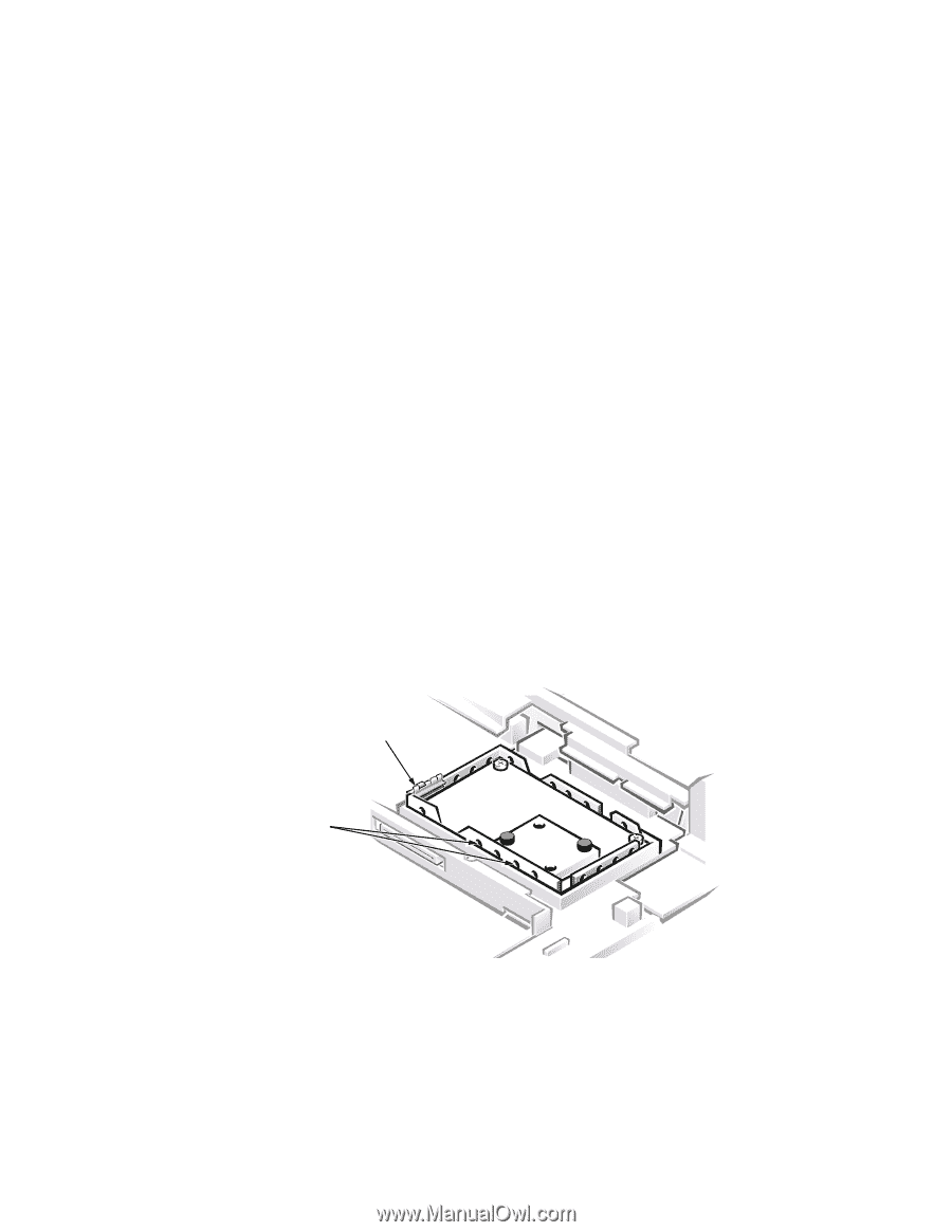
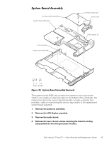
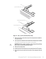
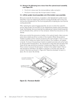
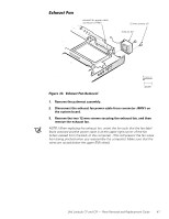
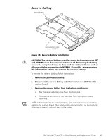
12. Remove the following two screws from the system board assembly (see Figure 30): The 5-mm screw near the reserve-battery cable connector The 5-mm screw near the microprocessor module 13. Lift the system board assembly out of the bottom case assembly. Be sure to transfer the memory module(s) to the replacement system board assembly. If you are replacing the thermal cooling assembly with a new one, remove any lining present on the thermal pad before installing the new thermal cooling assembly. After replacing the system board assembly, be sure to enter the system's service tag number into the BIOS of the replacement system board assembly. Insert the diskette that accompanied the replacement system board assembly into the diskette drive, and turn on the computer. Follow the instructions on the display. When you reinstall the processor module in the system board, make sure you press down evenly at all four corners of the module. When the processor module is seated, all four corners must be at the same height. If one or more corners of the module are higher than the others, the module is not seated correctly. To ensure the processor module is seated correctly, look at the holes on the processor-module fence. You should see no less than the top half of the holes all the way around the processor module (see Figure 32). Install the three screws to secure the processor module to the system board. Place a new processor hold-down clip (either a one-slot or two-slot clip) over the corner of the fence as shown in Figure 32. Press the clip down to lock it in place. Do not reuse the old clip. processor hold-down clip (one-slot clip shown) processor-module fence holes 46 Dell Latitude CP and CPi - Parts Removal and Replacement Guide
-
 1
1 -
2
-
3
-
4
-
5
-
6
-
7
-
8
-
9
-
10
-
11
-
12
-
13
-
14
-
15
-
16
-
17
-
18
-
19
-
20
-
21
-
22
-
23
-
24
-
25
-
26
-
27
-
28
-
29
-
30
-
31
-
32
-
33
-
34
-
35
-
36
-
37
-
38
-
39
-
40
-
41
-
42
-
43
-
44
-
45
-
46
-
 47
47 -
 48
48 -
 49
49 -
 50
50 -
 51
51 -
 52
52 -
 53
53 -
 54
54 -
 55
55 -
 56
56 -
 57
57 -
58
 |
 |