Dell Latitude CP Replacement Instructions - Page 4

LCD Inverter Board Removal 13.3-Inch Display .. 34

Page 4 highlights

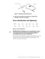
Module Latch Assemblies 41 Speakers 42 System Board Assembly 43 Exhaust Fan 47 I/R Board 48 Reserve Battery 49 Figure 1. Figure 2. Figure 3. Figure 4. Figure 5. Figure 6. Figure 7. Figure 8. Figure 9. Figure 10. Figure 11. Figure 12. Figure 13. Figure 14. Figure 15. Figure 16. Figure 17. Figure 18. Figure 19. Figure 20. Figure 21. Figure 22. Figure 23. Figure 24. Figure 25. Figure 26. Figure 27. Figure 28. Figure 29. Figure 30. Computer Orientation 1 Main Battery Assembly Removal 3 Screw Identification 3 Disconnecting an Interface Cable 4 Exploded View-Computer 14 Hard-Disk Drive Assembly Removal 15 Memory Module Cover Removal 16 Memory Module Removal 17 Keyboard Assembly Screws Removal 18 Keyboard Assembly Removal 19 Back Cover Assembly Removal 20 Palmrest Assembly Removal 21 Touch-Pad Interface Module Removal 23 Exploded View-Display Assembly (12.1-Inch Display Shown 25 Exploded View-Display Assembly (13.3-Inch Display Shown 26 Display Assembly Removal 27 Display Assembly Bezel Removal (12.1-Inch Display Shown 28 LCD Panel Removal (12.1-Inch Display 30 LCD Panel Removal (13.3-Inch Display 31 Magnet Holder 32 LCD Inverter Board Removal (12.1-Inch Display 33 LCD Inverter Board Removal (13.3-Inch Display 34 Display-Assembly Interface Cable Removal (12.1-Inch Display Shown 35 Bottom Case Assembly 37 Modular Bay Device Removal 38 Audio Board Removal 39 Bottom Case Bracket Removal 40 Module Latch Assemblies Removal 41 Left Slider 42 System Board Assembly Removal 43 iv

  • 1
  • 2
  • 3
  • 4
  • 5
  • 6
  • 7
  • 8
  • 9
  • 10
  • 11
  • 12
  • 13
  • 14
  • 15
  • 16
  • 17
  • 18
  • 19
  • 20
  • 21
  • 22
  • 23
  • 24
  • 25
  • 26
  • 27
  • 28
  • 29
  • 30
  • 31
  • 32
  • 33
  • 34
  • 35
  • 36
  • 37
  • 38
  • 39
  • 40
  • 41
  • 42
  • 43
  • 44
  • 45
  • 46
  • 47
  • 48
  • 49
  • 50
  • 51
  • 52
  • 53
  • 54
  • 55
  • 56
  • 57
  • 58

iv
Module Latch Assemblies . . . . . . . . . . . . . . . . . . . . . . . . . . . . . . . . . . . . 41
Speakers
. . . . . . . . . . . . . . . . . . . . . . . . . . . . . . . . . . . . . . . . . . . . . . . 42
System Board Assembly . . . . . . . . . . . . . . . . . . . . . . . . . . . . . . . . . . . . . 43
Exhaust Fan
. . . . . . . . . . . . . . . . . . . . . . . . . . . . . . . . . . . . . . . . . . . . . . 47
I/R Board . . . . . . . . . . . . . . . . . . . . . . . . . . . . . . . . . . . . . . . . . . . . . . . . . 48
Reserve Battery
. . . . . . . . . . . . . . . . . . . . . . . . . . . . . . . . . . . . . . . . . . . 49
±²³´µ
¶·¸¹º´»
Figure 1.
Computer Orientation . . . . . . . . . . . . . . . . . . . . . . . . . . . . . . . . . 1
Figure 2.
Main Battery Assembly Removal . . . . . . . . . . . . . . . . . . . . . . . . 3
Figure 3.
Screw Identification. . . . . . . . . . . . . . . . . . . . . . . . . . . . . . . . . . . 3
Figure 4.
Disconnecting an Interface Cable . . . . . . . . . . . . . . . . . . . . . . . . 4
Figure 5.
Exploded View—Computer . . . . . . . . . . . . . . . . . . . . . . . . . . . . 14
Figure 6.
Hard-Disk Drive Assembly Removal . . . . . . . . . . . . . . . . . . . . . 15
Figure 7.
Memory Module Cover Removal . . . . . . . . . . . . . . . . . . . . . . . 16
Figure 8.
Memory Module Removal. . . . . . . . . . . . . . . . . . . . . . . . . . . . . 17
Figure 9.
Keyboard Assembly Screws Removal. . . . . . . . . . . . . . . . . . . . 18
Figure 10.
Keyboard Assembly Removal . . . . . . . . . . . . . . . . . . . . . . . . . . 19
Figure 11.
Back Cover Assembly Removal. . . . . . . . . . . . . . . . . . . . . . . . . 20
Figure 12.
Palmrest Assembly Removal. . . . . . . . . . . . . . . . . . . . . . . . . . . 21
Figure 13.
Touch-Pad Interface Module Removal . . . . . . . . . . . . . . . . . . . 23
Figure 14.
Exploded View—Display Assembly
(12.1-Inch Display Shown)
. . . . . . . . . . . . . . . . . . . . . . . . . . . . 25
Figure 15.
Exploded View—Display Assembly
(13.3-Inch Display Shown)
. . . . . . . . . . . . . . . . . . . . . . . . . . . . 26
Figure 16.
Display Assembly Removal . . . . . . . . . . . . . . . . . . . . . . . . . . . . 27
Figure 17.
Display Assembly Bezel Removal
(12.1-Inch Display Shown). . . . . . . . . . . . . . . . . . . . . . . . . . . . . 28
Figure 18.
LCD Panel Removal (12.1-Inch Display) . . . . . . . . . . . . . . . . . . 30
Figure 19.
LCD Panel Removal (13.3-Inch Display) . . . . . . . . . . . . . . . . . . 31
Figure 20.
Magnet Holder. . . . . . . . . . . . . . . . . . . . . . . . . . . . . . . . . . . . . . 32
Figure 21.
LCD Inverter Board Removal (12.1-Inch Display) . . . . . . . . . . . 33
Figure 22.
LCD Inverter Board Removal (13.3-Inch Display) . . . . . . . . . . . 34
Figure 23.
Display-Assembly Interface Cable Removal
(12.1-Inch Display Shown). . . . . . . . . . . . . . . . . . . . . . . . . . . . . 35
Figure 24.
Bottom Case Assembly
. . . . . . . . . . . . . . . . . . . . . . . . . . . . . . 37
Figure 25.
Modular Bay Device Removal . . . . . . . . . . . . . . . . . . . . . . . . . . 38
Figure 26.
Audio Board Removal . . . . . . . . . . . . . . . . . . . . . . . . . . . . . . . . 39
Figure 27.
Bottom Case Bracket Removal
. . . . . . . . . . . . . . . . . . . . . . . . 40
Figure 28.
Module Latch Assemblies Removal . . . . . . . . . . . . . . . . . . . . . 41
Figure 29.
Left Slider . . . . . . . . . . . . . . . . . . . . . . . . . . . . . . . . . . . . . . . . . 42
Figure 30.
System Board Assembly Removal . . . . . . . . . . . . . . . . . . . . . . 43