Dell Latitude CP Replacement Instructions - Page 39
LCD Inverter Board, 12.1-Inch LCD Display
 |
View all Dell Latitude CP manuals
Add to My Manuals
Save this manual to your list of manuals |
Page 39 highlights
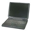
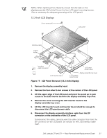
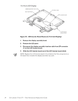
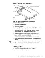
The following subsections describe how to remove an LCD inverter board from a 12.1-inch or 13.3-inch LCD display. display-assembly top cover connector J2 5-mm screws (2) spacers (2) LCD-assembly power cable LCD inverter board connector J1 1. Remove the display assembly bezel. 2. Disconnect the LCD-assembly power cable from connector J2 on the LCD inverter board. 3. Disconnect the display-assembly interface cable from ZIF connector J1 on the LCD inverter board. 4. Remove the two silver 5-mm screws and plastic spacers securing the LCD inverter board. Note the placement of the EMI shield over the lower screw boss, and the routing of the LCD-panel power cable around the upper screw boss. 5. Lift the LCD inverter board out of the display-assembly top cover. NOTE: When installing the inverter board, connect the LCD interface cable to the board prior to securing the board in the display-assembly top cover. After installing the inverter board, ensure that the LCD-panel power cable is routed around the plastic screw bosses in the display-assembly top cover. Dell Latitude CP and CPi - Parts Removal and Replacement Guide 33
-
 1
1 -
2
-
3
-
4
-
5
-
6
-
7
-
8
-
9
-
10
-
11
-
12
-
13
-
14
-
15
-
16
-
17
-
18
-
19
-
20
-
21
-
22
-
23
-
24
-
25
-
26
-
27
-
28
-
29
-
30
-
31
-
32
-
33
-
 34
34 -
 35
35 -
 36
36 -
 37
37 -
 38
38 -
 39
39 -
 40
40 -
 41
41 -
 42
42 -
 43
43 -
 44
44 -
45
-
46
-
47
-
48
-
49
-
50
-
51
-
52
-
53
-
54
-
55
-
56
-
57
-
58
 |
 |