Dell Latitude CP Replacement Instructions - Page 26
Back Cover Assembly, Grasp the right end of the back cover assembly firmly, and unsnap it
 |
View all Dell Latitude CP manuals
Add to My Manuals
Save this manual to your list of manuals |
Page 26 highlights
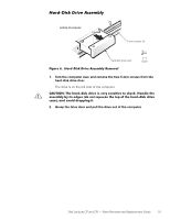
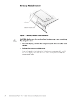
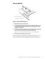
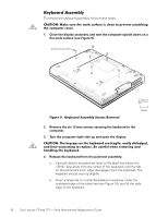
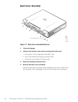
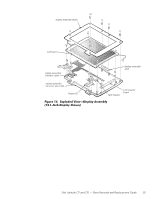
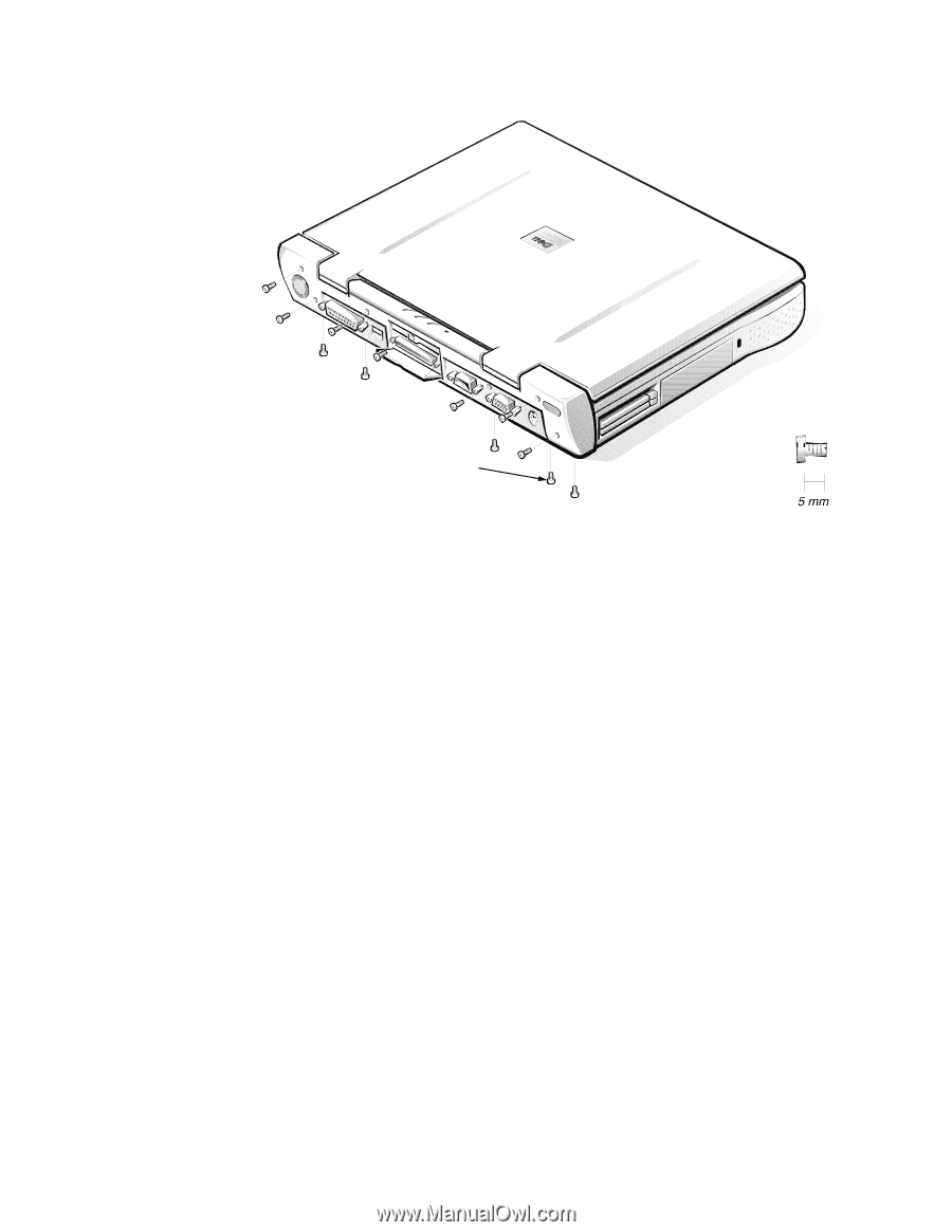
5-mm screws (12) 1. Close the display. 2. Remove the twelve 5-mm screws securing the back cover: Five screws on the underside of the back cover One screw behind the docking connector door Six screws on the face of the back cover 3. Close the docking connector door. 4. Remove the back cover assembly. Grasp the right end of the back cover assembly firmly, and unsnap it from the computer. Then disengage the left end of the back cover assembly. 20 Dell Latitude CP and CPi - Parts Removal and Replacement Guide
-
 1
1 -
2
-
3
-
4
-
5
-
6
-
7
-
8
-
9
-
10
-
11
-
12
-
13
-
14
-
15
-
16
-
17
-
18
-
19
-
20
-
 21
21 -
 22
22 -
 23
23 -
 24
24 -
 25
25 -
 26
26 -
 27
27 -
 28
28 -
 29
29 -
 30
30 -
 31
31 -
32
-
33
-
34
-
35
-
36
-
37
-
38
-
39
-
40
-
41
-
42
-
43
-
44
-
45
-
46
-
47
-
48
-
49
-
50
-
51
-
52
-
53
-
54
-
55
-
56
-
57
-
58
 |
 |
20
Dell Latitude CP and CPi
—
Parts Removal and Replacement Guide
DzȹºÅû¼³º½¸¸¼¾¿ÀÁº
±²³´µ¶·¸¸¹··ÄÁÎ/·º»Ë¶µ·ÆÇǶ¼ÈÉŷʶ¼»ËÁÉ·
1.
Close the display.
2.
Remove the twelve 5-mm screws securing the back cover:
±
Five screws on the underside of the back cover
±
One screw behind the docking connector door
±
Six screws on the face of the back cover
3.
Close the docking connector door.
4.
Remove the back cover assembly.
Grasp the right end of the back cover assembly firmly, and unsnap it from
the computer. Then disengage the left end of the back cover assembly.
5-mm screws (12)