Dell Latitude CP Replacement Instructions - Page 42
Display-Assembly Top Cover, Bottom Case Assembly, Remove the display assembly latch. - latitude cpi
 |
View all Dell Latitude CP manuals
Add to My Manuals
Save this manual to your list of manuals |
Page 42 highlights
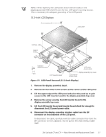
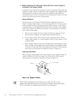
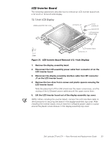
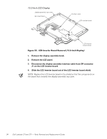
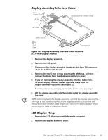
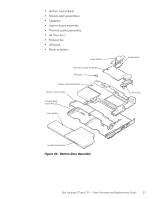
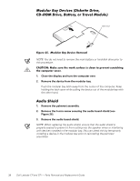
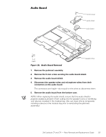
3. Remove the four silver 5-mm screws securing the two hinge brackets to the display-assembly top cover. NOTES: To aid in reinstalling the hinges and display assembly, the right and left hinges are marked by an "R" and an "L," respectively. Install the four screws securing the hinges at the locations marked by arrows on the face of each hinge. The right bracket on a 12.1-inch display fits above the right hinge (see Figure 14). 1. Remove the display assembly bezel. 2. Remove the display assembly. 3. Remove the LCD panel. 4. Remove the LCD inverter board. 5. Remove the display assembly latch. 6. Remove the left and right hinges. 7. Remove the right bracket (12.1-inch display only). 8. Remove the display-assembly interface cable. 9. If you are removing the display-assembly top cover from a 13.3-inch display, remove the right and left braces. To remove a brace, remove the 3-mm screw securing the brace to the display-assembly top cover. NOTES: The replacement display-assembly top cover assembly includes two badges, one for Dell Latitude CP and one for the Dell Latitude CPi. Look at the old cover to determine which badge is appropriate, and then attach the appropriate badge to the new cover. When reinstalling the display assembly, install the four screws securing the hinges at the locations marked by arrows on the face of each hinge. The bottom case assembly consists of the following field-replaceable components: Diskette drive assembly, CD-ROM drive assembly, or travel module Back cover assembly Audio shield Audio board 36 Dell Latitude CP and CPi - Parts Removal and Replacement Guide
-
 1
1 -
2
-
3
-
4
-
5
-
6
-
7
-
8
-
9
-
10
-
11
-
12
-
13
-
14
-
15
-
16
-
17
-
18
-
19
-
20
-
21
-
22
-
23
-
24
-
25
-
26
-
27
-
28
-
29
-
30
-
31
-
32
-
33
-
34
-
35
-
36
-
 37
37 -
 38
38 -
 39
39 -
 40
40 -
 41
41 -
 42
42 -
 43
43 -
 44
44 -
 45
45 -
 46
46 -
 47
47 -
48
-
49
-
50
-
51
-
52
-
53
-
54
-
55
-
56
-
57
-
58
 |
 |