Dell Latitude CP Replacement Instructions - Page 51
Verify that the PC Card ejectors do not extend from the PC Card bay.
 |
View all Dell Latitude CP manuals
Add to My Manuals
Save this manual to your list of manuals |
Page 51 highlights
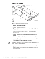
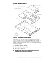
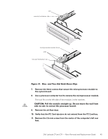
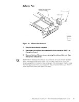
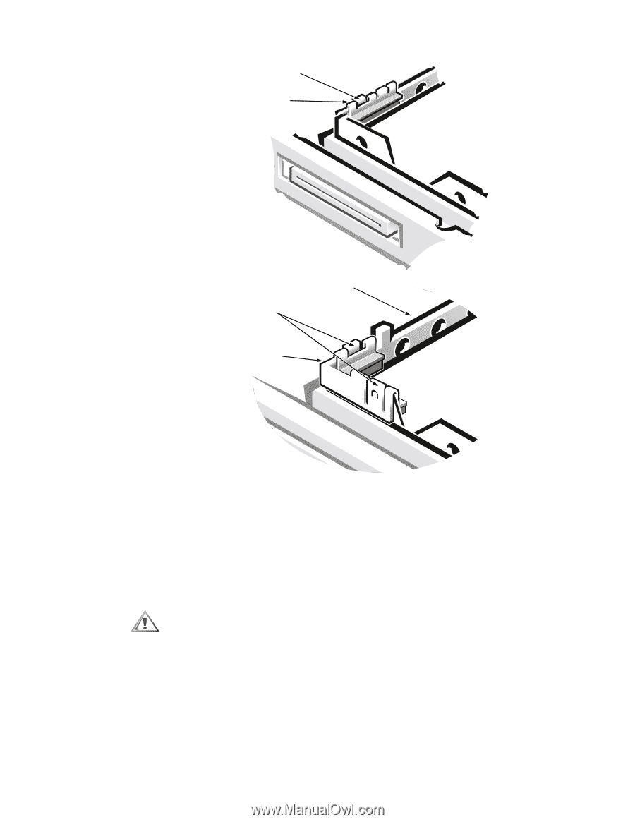
slot one-slot hold-down clip microprocessor-module fence slots two-slot hold-down clip 7. Remove the three screws that secure the microprocessor module to the system board. 8. Use a processor extractor tool to remove the microprocessor module. The tool fits on the left side of the module, in the notches. 9. Remove the air flow duct. 10. Verify that the PC Card ejectors do not extend from the PC Card bay. 11. Remove the 2.5-mm screw from the center of the computer's left rear foot. Dell Latitude CP and CPi - Parts Removal and Replacement Guide 45
-
 1
1 -
2
-
3
-
4
-
5
-
6
-
7
-
8
-
9
-
10
-
11
-
12
-
13
-
14
-
15
-
16
-
17
-
18
-
19
-
20
-
21
-
22
-
23
-
24
-
25
-
26
-
27
-
28
-
29
-
30
-
31
-
32
-
33
-
34
-
35
-
36
-
37
-
38
-
39
-
40
-
41
-
42
-
43
-
44
-
45
-
 46
46 -
 47
47 -
 48
48 -
 49
49 -
 50
50 -
 51
51 -
 52
52 -
 53
53 -
 54
54 -
 55
55 -
 56
56 -
57
-
58
 |
 |
Dell Latitude CP and CPi
—
Parts Removal and Replacement Guide
45
±²³´µ¶·Ì¸¹··¿À¶.·ÁÀ!·%Ï».ÍÉ»¾·-»É!.$»ÏÀ·ºÉ²½Ç
7.
Remove the three screws that secure the microprocessor module to
the system board.
8.
Use a processor extractor tool to remove the microprocessor module.
The tool fits on the left side of the module, in the notches.
±²³´µ¶·¸ /ËÅÅ ¾Á¿ ÆÄ»ËÅ¿ À¾Â½¹ÇÁ¾ ËÃÎ 3Ä ºÄ¾ ÆÄÌ¿ ¾Á¿ ¾ÄÄÅ ÉÂÄÆ
À¹»¿ ¾Ä À¹»¿ ¾Ä ¿7¾Â½¼¾ ¾Á¿ ÃÂļ¿ÀÀÄ ÍĽ»Î
9.
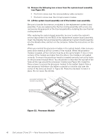
Remove the air flow duct.
10.
Verify that the PC Card ejectors do not extend from the PC Card bay.
11.
Remove the 2.5-mm screw from the center of the computer
’
s left rear
foot.
two-slot hold-down clip
slots
microprocessor-module fence
one-slot hold-down clip
slot