Dell Latitude CP Replacement Instructions - Page 34
Display Assembly Bezel, Remove the six screws from the bezel.
 |
View all Dell Latitude CP manuals
Add to My Manuals
Save this manual to your list of manuals |
Page 34 highlights
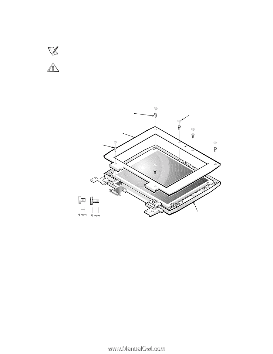
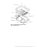
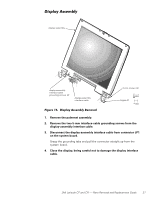
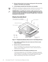
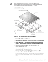
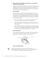
5. Remove the four silver 5-mm screws securing each of the two hinge brackets to the bottom case assembly. 6. Lift the display assembly from the bottom case assembly. NOTE: When reinstalling the display assembly, install the four screws securing the hinges at the locations marked by arrows on the face of each hinge. 5-mm screws (4) (12.1-inch displays); 3-mm screws (4) (13.3-inch displays) display assembly bezel 5-mm screws (2) screw covers (6) display-assembly top cover 1. Use a scribe to carefully pry the screw covers out of the six screw holes in the bezel. 2. Remove the six screws from the bezel. On 12.1-inch displays, all six screws are 5-mm screws. On 13.3-inch displays, the four upper screws are 3-mm screws, while the lower two screws are 5-mm in length. 3. Separate the bezel from the display-assembly top cover. If removing the bezel from a 12.1-inch display - The bezel is secured by snaps around all four of its edges. Insert your fingertips between the bezel and the LCD panel, and lift upward on the bezel to release the hidden snaps. Avoid pressing on the surface of the LCD panel. 28 Dell Latitude CP and CPi - Parts Removal and Replacement Guide
-
 1
1 -
2
-
3
-
4
-
5
-
6
-
7
-
8
-
9
-
10
-
11
-
12
-
13
-
14
-
15
-
16
-
17
-
18
-
19
-
20
-
21
-
22
-
23
-
24
-
25
-
26
-
27
-
28
-
 29
29 -
 30
30 -
 31
31 -
 32
32 -
 33
33 -
 34
34 -
 35
35 -
 36
36 -
 37
37 -
 38
38 -
 39
39 -
40
-
41
-
42
-
43
-
44
-
45
-
46
-
47
-
48
-
49
-
50
-
51
-
52
-
53
-
54
-
55
-
56
-
57
-
58
 |
 |